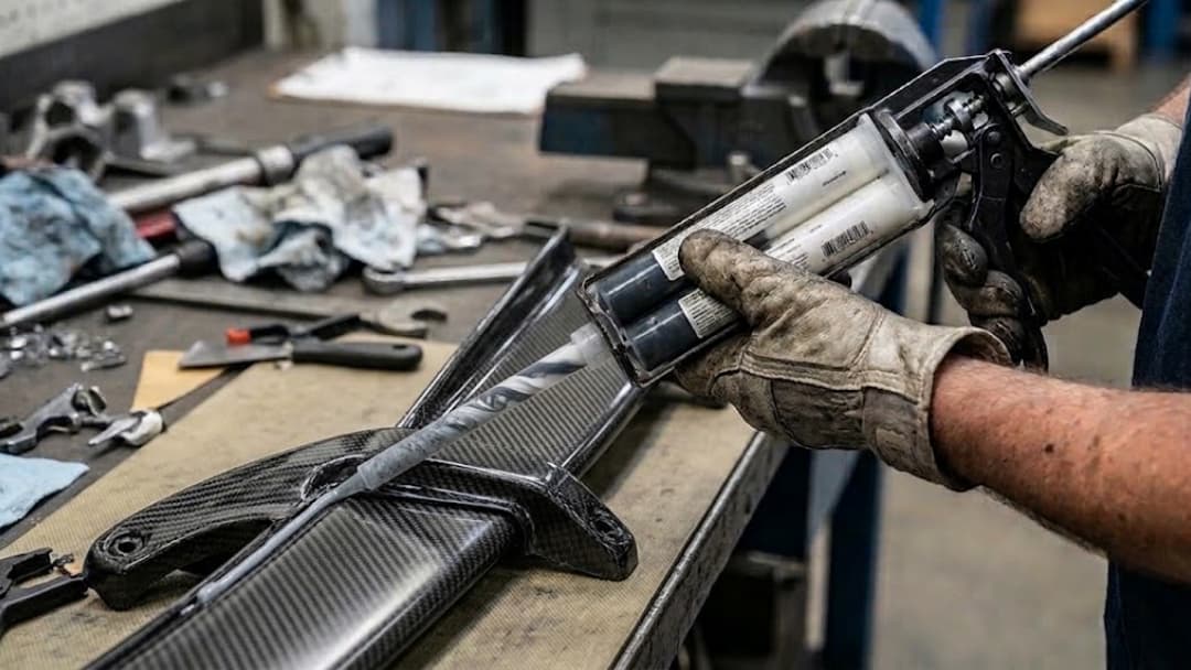
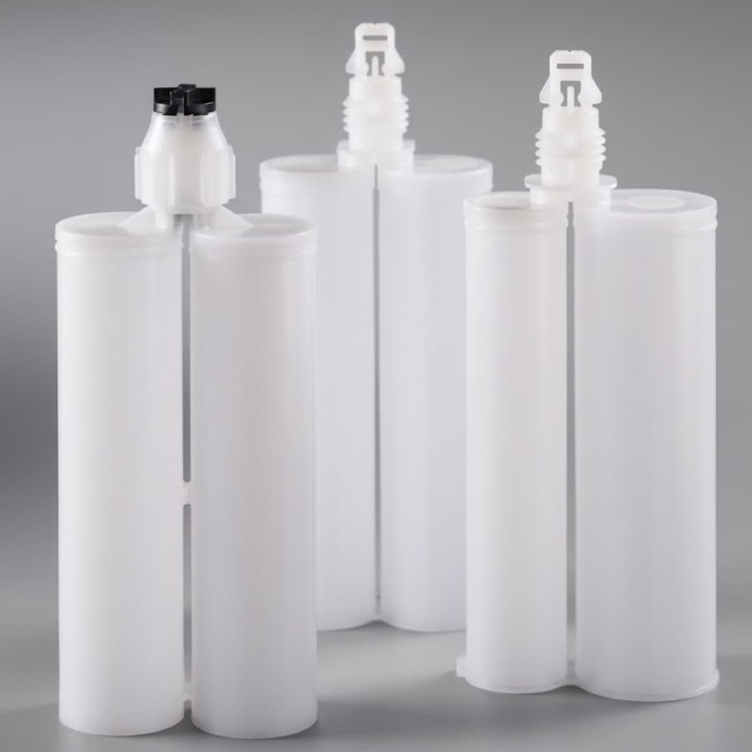
A dual cartridge epoxy gun can look correct and still be mechanically wrong. A purchasing description such as “400 ml, 2:1” leaves out the cartridge system, flange, barrel spacing, piston faces, retainer, mixer interface, and the evidence behind the tool’s available force. Those missing fields are where most avoidable selection failures begin.
Key Takeaways
- Start with the package. Freeze the cartridge drawing, system, volumetric ratio, size, and piston geometry before selecting a gun.
- Keep ratio definitions separate. The gun follows volumetric chamber geometry; an adhesive ratio stated by weight may be different.
- Do not treat nominal volume as a fit standard. Two 400 ml cartridges can require different frames, retainers, and plunger layouts.
- Read force fields literally. Mechanical thrust ratio, rated output force, and piston pressure are related but not interchangeable.
- Release a complete configuration. Approve the gun, plunger, cartridge, piston, mixer, adhesive, temperature, and work cycle together.
The working rule is simple: the package defines the gun, and the material-loaded trial decides whether that gun can be released. This guide turns that rule into a purchasing sequence, a published model matrix, and an approval record that engineering and procurement can use again.
Start With the Cartridge Specification
Do not begin a dual cartridge epoxy gun RFQ with the tool. Begin with the cartridge specification already approved for the adhesive. The gun is the drive mechanism around that package; it cannot repair an undefined ratio, an unknown flange, or an incompatible piston face.
The minimum input is a cartridge drawing or a controlled supplier part number. Record the cartridge family, nominal filled volume, volumetric ratio, barrel arrangement, flange, overall length, piston design, and outlet interface. Add the adhesive technical data sheet and the exact mixer. If any one of those items is provisional, mark the gun selection provisional too.
Link each package field to evidence and a mechanical decision:
- Cartridge system: use the drawing, family code, or approved sample to control the frame, retainer, flange support, and outlet access.
- Nominal volume: pair filled volume with overall dimensions to establish frame length, stroke, and the handling envelope.
- Volumetric ratio: use the chamber drawing and A:B designation to select the paired plunger geometry.
- Piston and outlet: use controlled drawings or samples to confirm plunger contact, mixer connection, sealing, and flow path.
“Two-part epoxy gun” is a function, not a complete specification. The related dual-component cartridge sizing guide explains the package variables in detail. Use it to establish the cartridge identity before comparing gun bodies.
Separate Volume Ratio From Weight Ratio
Two-component adhesive data can state mix ratio by volume, by weight, or both. These values are not automatically the same because Component A and Component B may have different densities. The cartridge and its paired plungers meter chamber volume. A gun must follow the package’s volumetric ratio, not a weight ratio copied from a formulation sheet.
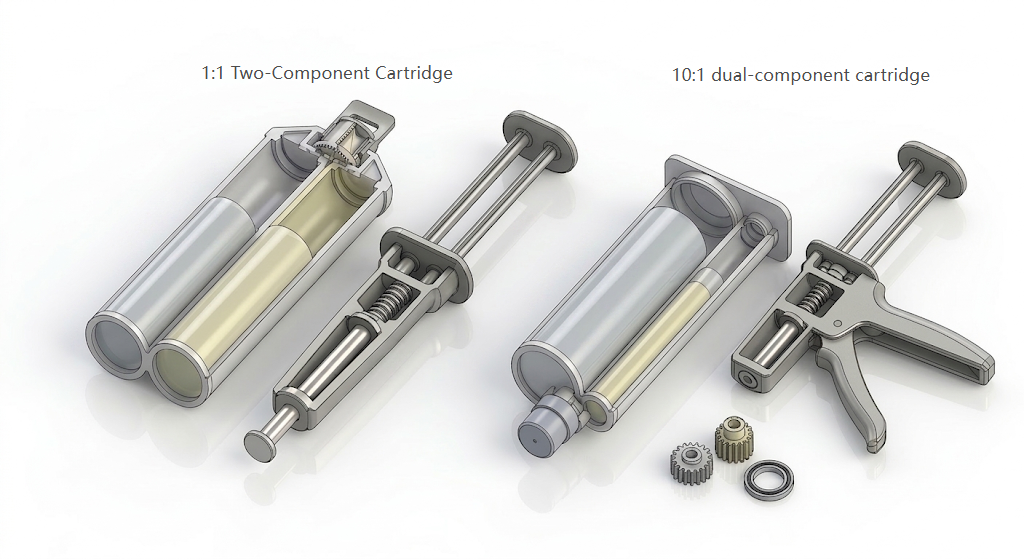
For a 1:1 package, equal piston travel across equal chamber areas displaces equal volumes. A 2:1, 4:1, or 10:1 package uses unequal chamber areas and the corresponding plunger geometry. The rods may move the same distance while the chambers discharge different volumes. That is expected behavior, not a calibration error.
The practical risk appears when an RFQ says only “epoxy ratio 2:1.” The buyer may mean weight ratio while the packaging supplier assumes volume ratio. Resolve that ambiguity in writing. The Machine Design discussion of dual-barrel dispensing also distinguishes weight and volume ratios and treats cartridge orientation and mixer fit as setup controls.
Match System Geometry Before Nominal Size
Nominal milliliters describe capacity, not a universal mechanical envelope. A 400 ml cartridge from one system may differ from another 400 ml package in barrel diameter, center distance, flange thickness, outlet position, piston depth, or overall length. A frame that closes around both packages is not proof that its push rods land squarely or that the retainer will hold under load.
Haijing’s recorded 400 ml 2:1 F-System cartridge, model F-CD400-21-PP-01-STD, gives a concrete example. Its documented chamber inside diameter is 45.59 mm, outside diameter is 52.44 mm, and overall length is 183.07 mm. These numbers identify one controlled configuration. They are not generic dimensions for every dual cartridge epoxy gun labeled 400 ml and 2:1.

Perform an empty-fit check before loading material:
- Seat the flange. It should rest fully in the intended support without bending, rocking, or forced closure.
- Check rod centering. Each plunger face should meet its cartridge piston squarely at the starting position.
- Lock the retainer. With the empty cartridge fully seated and the retainer closed, operate the release and advance controls only through manufacturer-permitted travel. Reject visible lift, rotation, forward shift, or off-center rod contact, and preserve photos of the starting and advanced positions.
- Run the travel. Verify clearance across the required stroke without contact between rods, frame, or cartridge walls.
- Install the mixer. Confirm the gun frame does not obstruct the outlet, retaining nut, or mixer inlet.
Use the Published Gun Compatibility Matrix
A model matrix narrows the search, but it does not eliminate the drawing and sample gates. Haijing’s current manual dispensing gun range includes the following recorded combinations. Each row proves a published model-to-ratio relationship; it does not promise compatibility with every cartridge carrying the same volume label.
| Published Gun Model | Recorded Format | Recorded Ratio | Required Release Check |
|---|---|---|---|
| A-DM50-11-05-STD | A-System 50 ml | 1:1 | Match exact cartridge and piston |
| A-DM50-11/21-01-STD | A-System 50 ml | 1:1 or 2:1 | Identify the installed plunger set |
| A-DM50-41-01-STD | A-System 50 ml | 4:1 | Confirm ratio-specific geometry |
| A-DM45-101-01-STD | A-System small format | 10:1 | Confirm exact package dimensions |
| C-DM200-11-01-STD | C/F-System 200 ml | 1:1 | Confirm retainer and flange |
| C-DM400-11-05-STD | C/F-System 400 ml | 1:1 | Confirm cartridge family and fit |
| C-DM600-11-01-STD | C-System 600 ml | 1:1 | Confirm complete stroke and support |
| F-DM400-11-01-STD | C/F-System 400 ml | 1:1 | Confirm the approved system record |
| F-DM400-21-01-STD | C/F-System 400 ml | 2:1 | Confirm 2:1 plunger and package |
The 50 ml rows are ratio-diverse small-format records, so the buyer’s first job is not choosing the strongest handle. Confirm the exact A-System cartridge and identify the installed plunger set; the 1:1/2:1 model especially needs a parts record showing which configuration was tested.
For 200 ml, the published C-DM200-11-01-STD row is 1:1 and is recorded for C/F systems. The sample must still prove flange seating, retainer fit, rod centering, and complete travel for the buyer’s cartridge. Do not infer a 2:1 option from the shared system label.
The 400 ml records include published 1:1 and 2:1 configurations across the listed C/F models. This is also where the documented F-System cartridge dimensions become useful: compare the buyer’s drawing with the 45.59 mm chamber ID, 52.44 mm OD, and 183.07 mm length example, then treat any difference as a new fit question rather than a tolerance assumption.
The 600 ml row has a narrower published boundary: C-DM600-11-01-STD is listed as a 1:1 C-System gun. Do not extend that row to an F-System or another ratio. Its release needs explicit confirmation of full stroke, frame support, mixer clearance, and material-loaded operation over the intended work position.
If the sample cartridge rocks, a rod begins off-center, one piston starts late, or the retainer lifts during advance, stop before adding force. These symptoms point to package identification, plunger geometry, or support—not to a need for a higher mechanical ratio.
Preserve the complete model code and installed parts on the purchase order, label, sample report, and receiving checklist. If a shared body supports multiple ratios, require a controlled parts list and record the plunger assembly used in the trial.
Read Thrust Data Without Guessing
Thrust terminology is often compressed into one catalog number. Separate it before making comparisons. A thrust ratio describes mechanical advantage in a manual drive. Output force is the force available at the plungers under stated conditions. Piston pressure depends on that force and the area over which it acts.
The physical relationship is pressure equals perpendicular force divided by area, or P = F/A, as defined in the OpenStax treatment of pressure. This does not create a safe shortcut from one supplier’s mechanical ratio to another supplier’s output rating. Handle geometry, losses, drive condition, piston area, and test method still matter.
There is also no responsible universal table that converts “epoxy viscosity” directly into a required gun ratio. The load is created by the complete path: material rheology and temperature, cartridge piston and seal friction, outlet opening, mixer diameter and length, application tip, desired bead rate, and any partial cure or blockage. One changed mixer can alter the result without changing the adhesive.
Read the force evidence as a hierarchy:
- Mechanical ratio describes how a manual mechanism multiplies input, not actual material flow.
- Rated output force states manufacturer-rated plunger force under defined test and operating conditions.
- Cartridge limits define what the exact package can safely accept at the relevant temperature.
- Flow-path data identifies the material, mixer, and outlet but cannot replace a complete-system trial.
- The material-loaded trial decides whether the recorded stack completes the required production cycle.
If the gun stalls, check for an unopened outlet, cured mixer, cold material, damaged piston, seal friction, or misalignment before increasing force. The broader adhesive dispensing gun guide covers general tool architecture.
Let Duty Cycle Choose the Drive
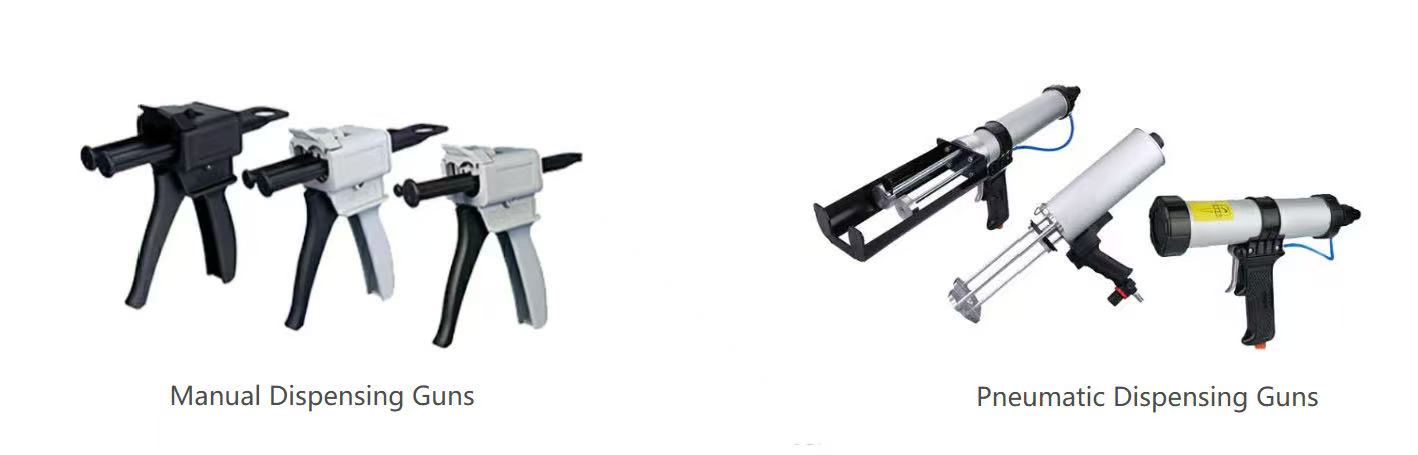
Once package compatibility and the evidence for force are clear, choose the drive from the work pattern. Manual tools suit intermittent beads, mobile work, samples, repair, and stations without utilities. They keep the setup simple but transfer repeated effort to the operator.
Pneumatic tools suit repeated production cycles where regulated plant air is already available. They can reduce trigger effort and support a steadier rhythm, but the air connection, control method, workstation, and approved pressure range become part of the process. An air-powered gun is not an automatic cure for a restrictive mixer or an undefined cartridge limit.
Use four questions to choose the drive:
- Where is the work? Field and moving-station tasks penalize air lines; fixed stations can support them.
- How often is the trigger cycled? Repetition increases the value of powered drive and controlled ergonomics.
- What force has been verified? Screen models using stated evidence, then test with production material.
- What control is actually required? A need for programmed shots or traceability may point beyond a handheld gun.
If the process needs automated metering, logged recipes, motion control, or integration with a production cell, reconsider the architecture instead of stretching a handheld epoxy applicator gun beyond its role. The adhesive dispensing systems guide provides that wider decision path.
Keep Cartridge, Gun, and Mixer Together
The gun does not operate alone. Its plungers act on cartridge pistons; the cartridge outlets feed a mixer; the mixer and any application tip create flow resistance; the adhesive and temperature determine the load. Procurement may place these items on separate lines, but engineering should release them as one dispensing stack.
Give the stack a configuration ID. That record should contain the complete gun model, plunger or conversion part, cartridge model, piston, mixer, adhesive grade, accepted material temperature range, bead or shot requirement, and approved work cycle. Add a photograph or drawing revision where visual identification helps.
The epoxy mixing nozzle buying guide explains how inlet fit and internal geometry affect that downstream decision. For this release, record the exact mixer part number used in the trial rather than a broad description such as “standard static mixer.”
Send the cartridge drawing before choosing the gun
Share the cartridge system, drawing, volumetric ratio, adhesive data, mixer, material temperature, and work cycle. Haijing can identify a sample configuration for fit and material-loaded approval.
Run a Material-Loaded Sample Approval
An empty fit check proves geometry at rest. It does not prove that the 2 part epoxy gun can purge, dispense, release, pause, and restart with the production adhesive. Do not use water or a convenient low-viscosity substitute as the final approval medium. The substitute removes the load that the trial needs to test.
Run a fixed sequence so each failure points to a defined stage. Photograph the empty assembly and record the controlled components. Load the production cartridge, install the approved mixer, condition the material to the test temperature, and follow the adhesive supplier’s purge instructions. Then complete the planned bead or shot pattern.
| Trial Stage | Record | Stop Condition |
|---|---|---|
| Empty fit | Seating, retainer, rod alignment, travel | Forced closure, rocking, or off-center contact |
| Initial purge | Both components present and purge method | One side missing, delayed, or visibly unequal |
| Working cycle | Bead or shot, cycle count, operator observation | Stall, package movement, leakage, or unsafe effort |
| Trigger release | Tail, drip, residual piston movement | Uncontrolled flow outside the accepted process |
| Pause and restart | Pause time and first restarted output | Blockage, streaking, or abnormal discharge |
| End of stroke | Piston travel, retained material, package condition | Unequal travel, damaged piston, or cartridge failure |
The signed result should identify approver, date, adhesive batch, temperature, cycle, and every controlled component. Approval belongs to that configuration, not to a generic gun family. Retain the record with a photographed reference or approved sample where practical.
Write an RFQ That Prevents Substitution
A useful RFQ transfers a controlled engineering decision into a supplier quotation. It should not ask the supplier to infer the cartridge from a photo or select “something strong enough.” State the package, ratio basis, flow path, work cycle, and evidence required for acceptance.
Include these fields in the RFQ and purchase specification:
- Package identity: cartridge supplier, system, part number, drawing revision, nominal volume, ratio by volume, flange, and piston.
- Gun identity: complete model code, drive, installed plunger, retainer, conversion parts, and label requirements.
- Material and path: adhesive grade, test temperature, mixer part number, outlet or extension, and required bead or shot.
- Work pattern: cycles, pauses, operating position, mobility, utilities, and operator constraints.
- Acceptance evidence: drawing, parts list, rated data, sample report, inspection record, and approved configuration ID.
- Change control: no material, geometry, model, or component substitution without written buyer approval.
Make acceptance observable. “Suitable for high-viscosity epoxy” cannot be measured. “Completes the recorded purge, bead, release, pause, and restart sequence without a stall, leak, cartridge movement, or package damage” can be witnessed and signed.
For receiving, require model and ratio labels that remain readable after unpacking. Similar gun bodies should not be sorted by handle color or visual memory. The purchase order, carton list, tool label, and inspection record should preserve the same full code.
Plan MOQ, Samples, and Lead Time
Commercial planning starts after a technically plausible configuration is identified. Haijing’s documented minimum order for 50, 75, and 100 ml dispensing guns is 50 pieces. The documented minimum for 200, 400, and 490 ml guns is 10 pieces. Request a quoted MOQ for a 600 ml or custom configuration rather than extending those rows by assumption.
Samples sit outside the bulk MOQ. The buyer pays the sample and freight charges, and the documented sample lead time is 3–7 days. The recorded production lead time for dispensing guns is 1–2 weeks. Both schedules depend on the exact model and order details being agreed.
Convert the published commercial terms into controls:
- 50/75/100 ml guns: plan around the 50-piece MOQ and separate each model and ratio as a controlled SKU.
- 200/400/490 ml guns: plan around the 10-piece MOQ and fix the system, retainer, and plunger in the order.
- Samples: treat them as production-intent configurations outside bulk MOQ; the buyer pays sample and freight.
- Timing: count the 3–7 day sample and 1–2 week gun-production windows after configuration confirmation.
Haijing can provide inspection reports, first article inspection reports, STEP or IGES models, and chemical compatibility charts where applicable. Select the evidence that supports the released interfaces.
Use the Final Release Checklist
The release gate should be short enough to use on every new configuration and strict enough to stop a vague order. Ownership matters. Packaging engineering should close the package, ratio, and empty-fit gates. Process engineering should own force evidence, the complete flow path, and the signed material trial. Procurement should not issue the production order until the model, documents, and change rule are complete.
A failed gate returns the configuration to its owner. An off-center rod goes back to package and tool matching; a cold-condition stall goes back to flow-path and force validation; an unlabeled ratio variant stays out of purchasing. This routing prevents a commercial deadline from converting missing evidence into an assumed approval.
Release the dual cartridge epoxy gun only when all seven answers are yes:
- Package defined. System, model, drawing revision, volume, flange, piston, and outlet are recorded.
- Ratio defined. The A:B volumetric ratio and the installed plunger geometry match.
- Fit proven. Empty seating, retainer security, rod alignment, mixer access, and travel pass.
- Force supported. Manufacturer data screens the model and the real-material trial completes the required cycle.
- Complete path frozen. Adhesive, temperature, cartridge, piston, mixer, tip, and work pattern match the test.
- Sample signed. Purge, bead or shot, release, pause, restart, and end-of-stroke checks pass.
- Order controlled. Model, parts, labels, evidence, MOQ, timing, receiving, and change rules are written.
The signed page becomes a handoff record. Receiving uses the model and labels, production uses the configuration and test conditions, and quality uses the stop conditions. If any team cannot identify its field, the release remains open even when a supplier has already quoted the tool.
Freeze the Released Configuration
The conclusion becomes useful at reorder, not at first quotation. Store one approved photograph or retained sample beside the drawing revision and signed test. When a shipment arrives, receiving should be able to compare the full model label, installed plunger, retainer, and visible cartridge seating without reconstructing the original decision.
If a supplier proposes a revision, compare it with that golden reference and reopen only the gates affected by the change. A new label with unchanged controlled parts may require a document review; a new plunger, retainer, mixer, cartridge, material condition, or work cycle requires the relevant fit or dispensing checks again. This targeted change review keeps reorders efficient without turning similarity into equivalence.
A dual cartridge epoxy gun is ready to buy when its released state can be recognized, tested, and repeated by people who were not present at the first sample. Send the cartridge drawing and process inputs to Haijing when you need a model review built around that standard.
When cartridge and plunger fit are approved, continue with the pneumatic dispensing gun commissioning guide to validate working pressure, purge, cutoff, and fault isolation.
A dispenser can be approved only against a released package. Use the empty cartridge filling and storage guide to document body, piston, cap, outlet, fill process, and package-aging evidence before freezing the field tool.
When a released tool and cartridge configuration later fails, the 2K cartridge failure-analysis process shows what to quarantine, photograph, compare, and send to each supplier.
Frequently Asked Questions
Can a 1:1 gun be converted to 2:1 by changing only the push plate?
Do so only when the supplier identifies a controlled conversion assembly for the exact cartridge. Record every changed part, repeat the empty-fit checks, and rerun the material-loaded trial before release.
What should I do if a cartridge fits the frame but the rods are off-center?
Reject the fit. Photograph the starting contact, compare the cartridge and gun drawings, and request the correct configuration. Do not bend the frame or let the rods self-align under material load.
What if epoxy flows warm but the gun stalls at the lowest approved temperature?
The warm result does not cover the approved process range. Condition the complete stack at the lower temperature, repeat the defined cycle, and resolve the material, mixer, or tool restriction from that recorded result.
Does changing the static mixer invalidate gun approval?
Reopen the affected checks if connection geometry or flow restriction changes. At minimum, confirm fit, purge, working force, trigger release, pause, and restart with the replacement mixer.
When is a handheld epoxy gun the wrong architecture?
Move beyond a handheld tool when the process requires programmed shots, recipe control, traceability, or coordinated motion. Those needs belong in a metering or automated dispensing-system review.