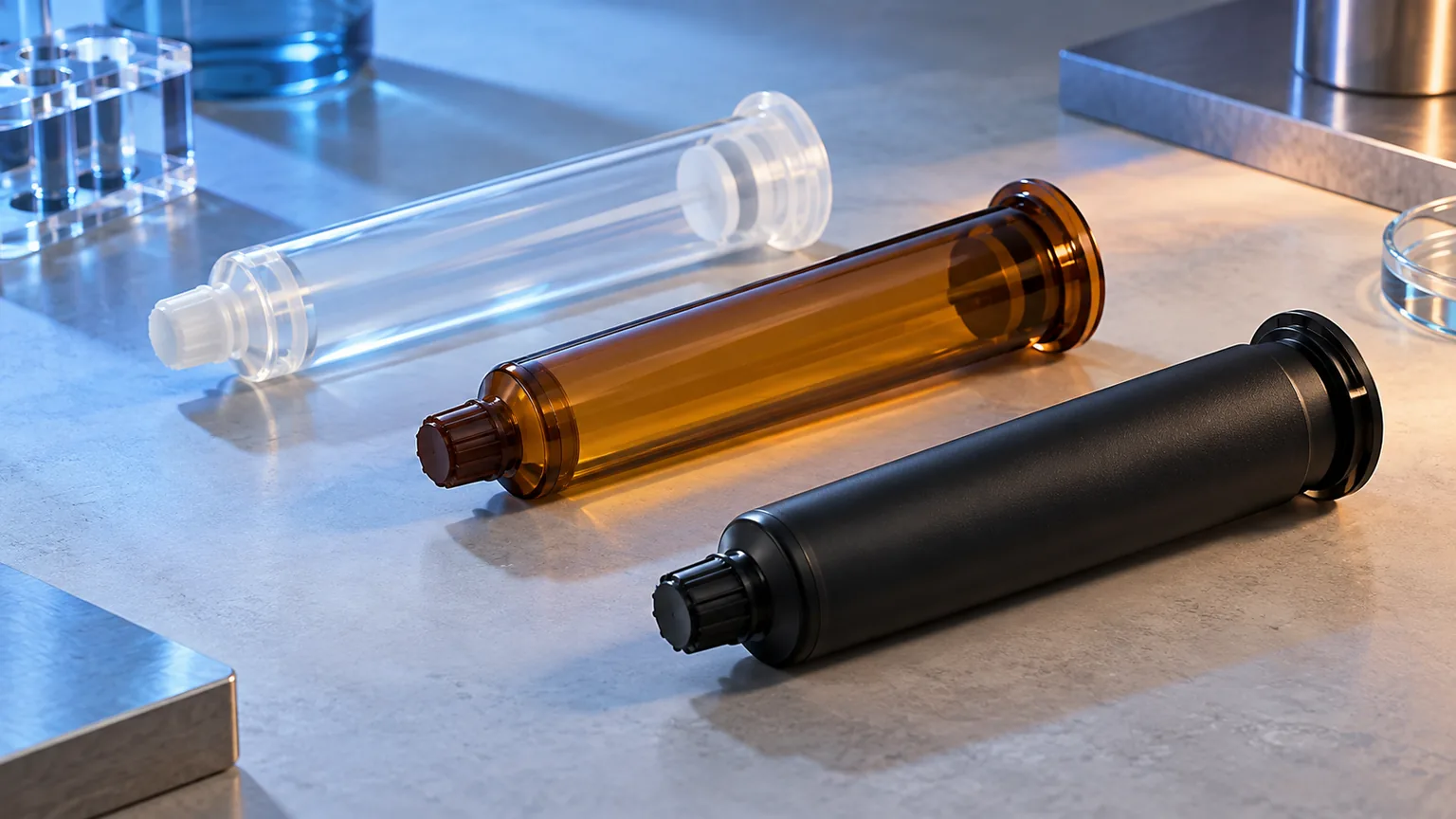
The most expensive mistake in adhesive dispensing systems often happens before anyone compares machines. A team chooses an applicator, then tries to force the material package, mixer, controls, and inspection plan around it. The hardware may run, yet the deposit can still miss its ratio, shape, location, or cure requirement.
In short: define the accepted deposit first, then work backward through the outlet, mixer, metering method, drive, and material supply. Choose the simplest architecture that can hold those linked conditions through startup, steady production, pauses, restarts, and changeovers.
Key Takeaways
- Start with the deposit. Define material, location, amount, pattern, production rate, and acceptance evidence before selecting equipment.
- Treat every interface as controlled. Package, gun, ratio, mixer inlet, element geometry, and outlet must work as one approved chain.
- Separate fluid delivery from motion. A robot can position a nozzle, but it cannot repair unstable feed, wrong component ratio, or poor mixing.
- Test the real process. Use production-representative material and parts through startup, continuous running, pauses, restarts, and changeovers.
- Freeze the approved configuration. A replacement cartridge, mixer, pump, or control setting can change the deposit even when its catalog description looks similar.
Quick Selection Snapshot
- Selection order
- Deposit → outlet → mixer → meter and drive → material supply
- Architecture choices
- Manual, pneumatic, meter-mix, or automated motion
- Documented cartridge range
- Dual-component formats from 50 to 1500 ml across the portfolio
- Documented ratios
- 1:1, 2:1, 4:1, and 10:1 across dual-cartridge families
- Static mixer families
- A-, B-, C-, and F-System connection concepts
- Dynamic mixing boundary
- Machine-use designs documented up to 100:1
Define the Process Before Equipment
An adhesive dispenser is not the process. The process is the controlled conversion of stored material into an accepted dot, bead, fill, spray, or potting volume on a part. Equipment earns its place only when it can deliver that result across the full production cycle.
Write the deposit requirement in measurable terms your team can inspect. Name the material and package, one-component or two-component condition, target location, output form, cycle pattern, pause history, and cure check. If a value is still unknown, label it for trial instead of hiding it behind “high precision.”
This order prevents a common ownership gap. Procurement may buy the machine, engineering may choose the adhesive, and production may inherit the cleaning burden. A single system sheet forces those decisions into one record before a purchase order makes the boundaries expensive to change.
Map the Container to Deposit Chain
Every industrial adhesive dispensing system has a chain, even when several functions share one compact tool. Material starts in a syringe, cartridge, bottle, pail, drum, or other package. A drive or feed method moves it, a metering stage controls quantity, and a mixer combines components when the chemistry requires it.
The outlet shapes the material at the point of application. A fixed fixture, coordinate applicator, or robot controls where that outlet travels. Controls issue commands, while sensors and inspection decide whether the result deserves release.
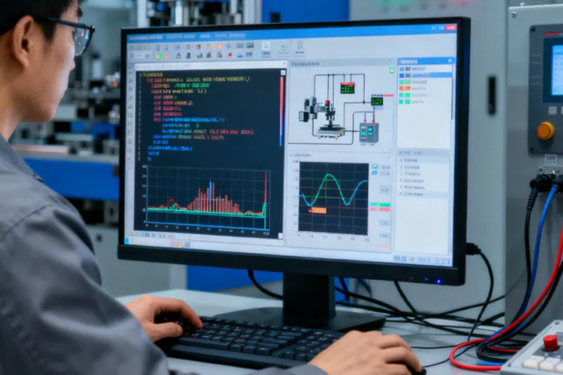
Industry equipment catalogs group the chain around material delivery, controllers, dispense robots, meters, hoses, applicators, and nozzles. That taxonomy is useful, but buyers still need an interface map. Two devices in the same category can demand different packages, utilities, outlets, cleaning methods, or evidence.
| System Stage | Decision It Owns | Typical Hardware | Evidence to Capture |
|---|---|---|---|
| Material supply | Condition and continuity | Syringe, cartridge, vessel, pump | Material lot and package |
| Drive and feed | How material moves | Manual, pneumatic, electric, pump | Force or pressure trend |
| Meter and ratio | How much exits | Plungers, valves, metering pumps | Shot or component output |
| Mix and outlet | Condition at deposit | Static mixer, dynamic mixer, tip | Bead and cure result |
| Motion and control | Where and when | Fixture, axes, robot, PLC | Path, timing, alarms |
This table is a boundary tool, not a shopping list. Assign one owner to each stage and record the handoff between stages. A leak at the cartridge outlet can look like a mixer problem; a weak drive can look like excessive viscosity; poor part location can look like unstable bead control.
Start With Material and Package
Begin with the adhesive maker’s technical data and the material as it reaches production. Record whether it is ready to dispense or needs component ratio control and mixing. Note the package, cure mechanism, filled or unfilled condition, and temperature state used during the trial.
TWI divides reactive adhesives broadly into one-component and two-component systems. One-component material can move from its package to an outlet without on-line mixing. Two-component material must remain separated until the controlled mixing point, so ratio delivery and the junction between the two streams become process functions.
Package format is not a minor purchasing detail. It sets the holder, plunger arrangement, refill event, exposure during changeover, and available feed methods. A 2K cartridge carries a mechanical ratio in its chamber geometry; a bulk meter-mix system establishes ratio through its metering hardware.
Three material paths set different control boundaries:
- 1K package — control material condition and output; release the process on deposit and cure evidence.
- 2K cartridge — control chamber ratio and plunger travel; mix after the outlet and verify both streams, bead, and cure.
- 2K bulk feed — control each component’s metering; validate the static or dynamic mixer plus the mixed result.
Do not assign a universal viscosity limit from an article. Viscosity changes with formulation and operating condition, while equipment capability depends on its complete fluid path. Give the supplier the real material data, then confirm flow and restart behavior in the representative trial.
Choose the Right Metering Path
Dispense-only systems move a ready material and control its release. Their simplicity makes them strong candidates for flexible work, field assembly, prototyping, and production cells where the package already protects material condition. The trade-off is that output can depend more heavily on the operator or time-pressure state.
A dual cartridge uses matched plungers and chamber geometry to advance two materials together. This route reduces the number of wetted machine components and keeps changeover centered on a packaged set. It still needs the correct gun, cartridge ratio, outlet interface, and mixer.
Meter-mix equipment meters two feeds before combining them. It suits processes that need a supply architecture beyond packaged cartridges, but it introduces pump, hose, calibration, cleaning, and maintenance decisions. The system cannot be judged from a headline ratio alone.
Dynamic mixing adds powered motion at the mixing stage. Haijing’s documented machine-use dynamic mixer range covers ratios up to 100:1 and targets large viscosity differences or shear-sensitive materials. Treat that as a candidate boundary, then validate the actual formulation and process.
Use this order when narrowing the metering path:
- Confirm the package — identify what production will actually load, not the laboratory container.
- Define ratio ownership — state whether the cartridge or the metering equipment controls component delivery.
- Locate the mixing point — freeze the junction, mixer interface, geometry, and outlet as linked fields.
- List restart evidence — require output and cure checks after the longest planned pause.
Compare the Four System Architectures
The choice depends on the rejected risks behind each architecture. A manual tool is not “low grade,” and a robot is not automatically “high quality.” Each architecture controls a different part of the process.
- Manual cartridge: best for flexible, low-volume work and simple package changes when the acceptance plan can tolerate operator-driven output.
- Pneumatic cartridge: adds powered, steadier drive for repeated packaged dispensing, with compressed air and setup as added requirements.
- Meter-mix: provides independent component metering when cartridge supply becomes limiting, with more wetted hardware to calibrate and maintain.
- Automated motion: programs repeated locations or paths after fluid delivery is stable, while adding fixturing and integration work.
Choose manual cartridge dispensing when flexibility and fast material change matter more than automated placement. Choose pneumatic cartridge dispensing when the package is right but operator force cannot hold repeatable output through the duty cycle. Both routes can support 1K or 2K packages when their hardware matches.
Choose meter-mix when component supply and ratio control need a machine-level architecture. Do not make that step only because a process uses two components; a validated dual-cartridge route may remain the cleaner answer for the required volume and changeover pattern.
Add automated motion when deposit location or path needs programmed repeatability. Stabilize fluid delivery first. A moving nozzle attached to an unstable feed simply repeats an unstable deposit along a more accurate path.
Worked Selection Scenario: A Packaged 2K Cell
Consider an illustrative assembly project with a production-approved two-component adhesive, a project-defined 400 ml cartridge at 2:1, and a repeated bead on a part held in a fixed fixture. The plant has compressed air, the path repeats, and production has already named its longest planned pause. These are bounded project inputs for demonstrating the method; they do not claim that every 400 ml cartridge shares one outlet, gun, or mixer.
- Choose the architecture. Keep the approved packaged ratio instead of adding bulk meter-mix equipment. Use a pneumatic cartridge drive because the plant has air and the team needs powered output. Add coordinate motion only because the bead path repeats; a general-purpose robot adds no clear process control to this bounded case.
- Freeze the interfaces. Record the exact cartridge drawing, 2:1 plunger relationship, holder and travel, outlet connection, mixer inlet family, element specification, final tip, and fixture stand-off. The nominal capacity and ratio cannot substitute for these interface fields.
- Plan the trial. Use the production adhesive and parts. Record material lots and component codes, observe both streams before mixing when practical, then capture purge, first accepted bead, a steady sequence, the planned pause, restart, mixed appearance, and cured result.
- Release or reject. Release the configuration only if every recorded result meets the project’s prewritten deposit and cure criteria. If restart fails while steady running passes, reject the release as written and test a revised purge, mixer-change, or pause rule. Do not hide that failure by averaging it with accepted beads.
This case selects a pneumatic packaged system with coordinate motion because each choice removes a named variable. A different package, duty cycle, part presentation, or acceptance plan can change the result. The reusable output is the decision record, not the example hardware combination.
Match Cartridge Gun and Ratio
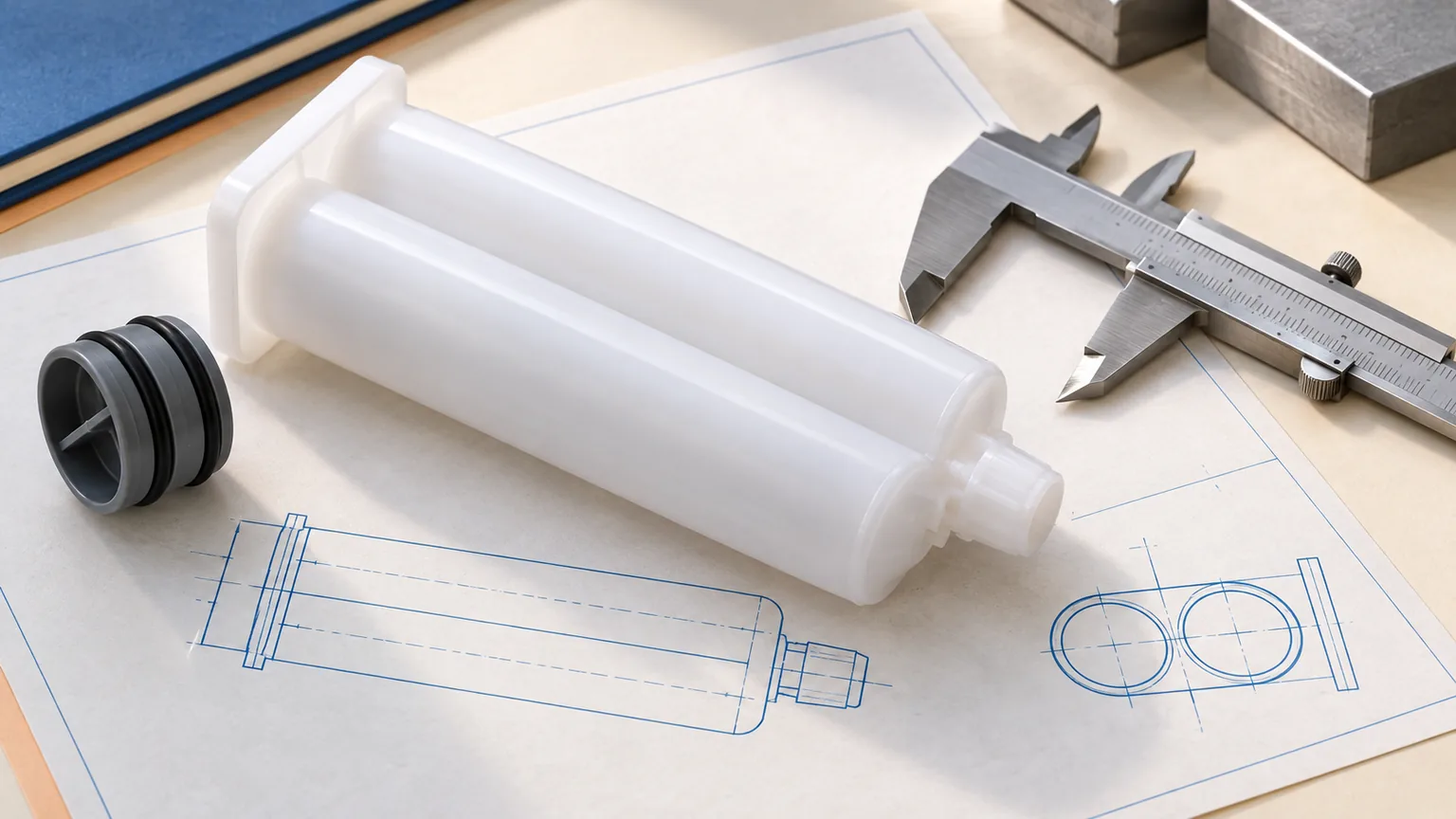
Cartridge compatibility has three layers: the cartridge must fit the holder, the drive must engage the correct piston arrangement, and the outlet must mate with the intended tip or mixer. Matching only the nominal capacity leaves two interfaces unchecked.
Haijing’s documented dual-component portfolio includes 50, 75, 100, 200, 400, 600, and 1500 ml formats. Available configurations across the portfolio include 1:1, 2:1, 4:1, and 10:1. The single-component range lists 100, 200, 300, 310, 400, 500, 1000, and 2600 ml.
Those numbers describe available families, not universal interchangeability. The gun still needs the matching frame, plunger relationship, and mechanical travel. For a broader package review, record the exact drawing or model code in the RFQ.
Freeze these fields as one cartridge-drive specification:
- Package family and capacity — record the exact format, not a rounded market description.
- Component ratio — match chamber geometry and the gun’s plunger arrangement.
- Retainer and travel — verify seating, piston contact, full stroke, and removal.
- Outlet interface — name the cap, tip, or mixer connection and its sealing surfaces.
- Material contact — approve the cartridge polymer with the actual formulation and storage condition.
Select the Mixer and Outlet
A two-component stream is not finished when both pistons move. The mixer must accept the outlet, keep the components in their intended paths before mixing, provide suitable internal geometry, and deliver the required bead through its tip.
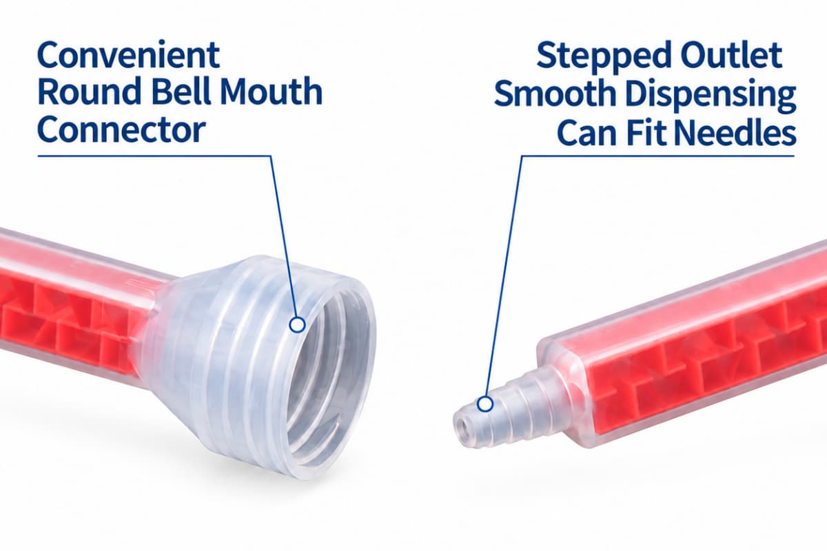
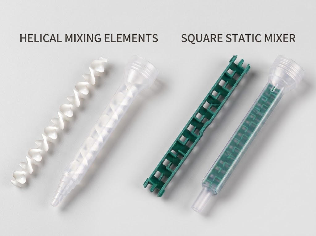
Haijing’s A-, B-, C-, and F-System static mixers serve different cartridge and inlet families. The range covers bayonet, separated-port, threaded, and positive-stop connection concepts. Ratios and cartridge sizes vary by family, so a familiar outside shape is not sufficient evidence of compatibility.
Element count, length, material, and outlet can be customized. Standard documented outlet forms include stepped tips and Luer Lock connections. Each change can affect retained material, resistance to flow, bead delivery, and the tool or machine load, so compare candidates under the same test conditions.
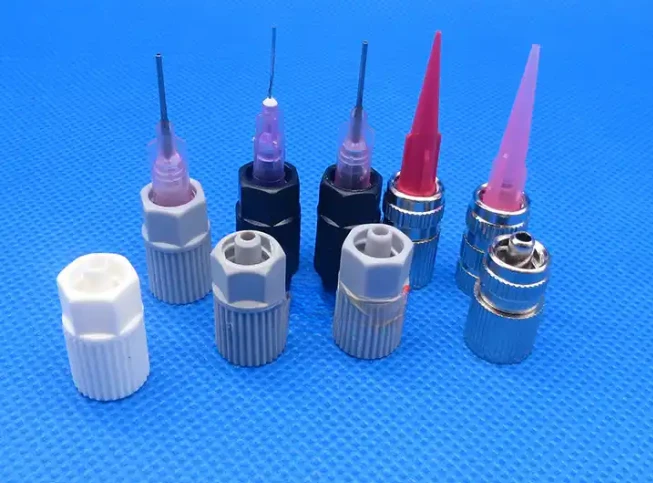
Use a static mixer when the passive geometry can produce the accepted result within the available drive or pressure boundary. Evaluate a dynamic mixer when the formulation and ratio create a stronger mixing challenge. The detailed trade-off belongs in the static versus dynamic mixing guide.
| Component | Documented Haijing Range | Interface to Freeze | Trial Evidence |
|---|---|---|---|
| Dual cartridge | 50-1500 ml; 1:1-10:1 | Holder, plungers, outlet | Fit and component delivery |
| Single cartridge | 100-2600 ml formats | Thread, piston, drive | Leak and deposit |
| Static mixer | A, B, C, F families | Inlet, elements, outlet | Mix, load, bead, cure |
| Dynamic mixer | Machine use; up to 100:1 | Feed, motor, element | Mix under duty cycle |
Need Components for a Dispense Trial?
Send the adhesive package, component ratio, target deposit, and drive method. Ask for compatible cartridges, mixers, or guns to test with your production material and acceptance record.
Cartridges | Static and dynamic mixers | Manual and pneumatic guns
Set the Right Automation Boundary
Automation can control a trigger, a timed shot, a fixed station, a coordinate path, or a robot cell. These are different boundaries. Ask which uncontrolled variable the project needs to remove before choosing a motion platform.
A fixed or benchtop station can be enough when parts arrive in one repeatable location and the deposit does not need a complex path. A coordinate applicator adds programmable axes for repeated dots, lines, or patterns. A robot earns its complexity when part geometry, orientation, reach, or cell integration needs it.
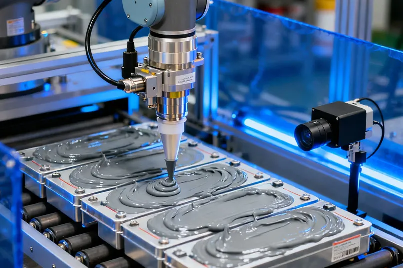
Keep fluid and motion acceptance separate. First prove that the stationary system can supply an acceptable deposit. Then prove that motion holds location, speed, starts, corners, and stops without changing the output beyond the project’s limits.
Part presentation belongs in this decision. A precise path program cannot repair an inconsistent fixture or unknown part offset. Vision can measure and compensate for selected variation, but the team must define what the camera finds, how the path changes, and what result causes rejection.
Do not compress every automation question into this pillar. Fixed automation versus robot architecture needs its own throughput, flexibility, safety, programming, and integration comparison. This page defines where that later decision starts.
Specify Controls and Required Evidence
A command is not proof of output. A controller may request a time, pressure, motor move, valve state, or pump displacement. The released process still needs an observable result tied to that command.
Choose evidence from the actual failure path. For a metered shot, weight or volume may expose output drift. For a bead, width, height, continuity, and location may matter. For 2K material, separate component output, mixed appearance, and cured result can answer different questions.
Pressure or drive-force trends can support diagnosis, but they do not replace deposit inspection. A rising load can point to restriction, material condition, or a changing mixer. The same signal cannot name the cause without a controlled comparison.
| Control Layer | Command | Observable Evidence | Release Question |
|---|---|---|---|
| Material supply | Feed state | Lot, level, condition | Was the right material available? |
| Dispense | Time, force, pressure, move | Output weight or volume | Did the requested amount exit? |
| Motion | Path and speed | Deposit position and shape | Was material placed correctly? |
| 2K mix | Component delivery | Streams, mix, cure result | Did the material combine correctly? |
| Quality | Inspection sequence | Recorded pass or reject | Can the result be released? |
Set alarms around conditions the system can actually observe. If no sensor measures a variable, do not imply that software controls it. Put the missing risk into an inspection or trial step until the architecture includes a suitable measurement.
Build the System Selection Worksheet
A useful RFQ lets two suppliers quote the same problem. It also lets production recognize when a proposed substitution changes the approved system. Start with the worksheet below, then attach drawings, material data, and part images where words leave room for interpretation.
| Field | Required Input | Owner | If Unknown |
|---|---|---|---|
| Adhesive | Name, 1K/2K, data sheet | Materials engineering | Get supplier data |
| Package | Type, capacity, ratio, drawing | Packaging or procurement | Test candidate formats |
| Deposit | Dot, bead, fill, location | Process engineering | Create part samples |
| Production | Cycle, run, pause, changeover | Operations | Observe pilot work |
| Acceptance | Output, position, mix, cure | Quality | Define trial criteria |
| Integration | Utilities, signals, motion, safety | Automation | Map cell interfaces |
For 2K cartridges, add both component names, mix ratio, cartridge family, outlet style, gun or actuator, mixer inlet, element geometry, and final outlet. For bulk feed, add supply container, transfer method, metering principle, hose path, mixer, cleaning plan, and calibration evidence.
Separate requirements from preferences. A required cure result belongs in the acceptance column. A preferred cabinet color does not. This distinction keeps the supplier focused on the interfaces that can stop production or invalidate the deposit.
Reject a quotation that leaves these boundaries unnamed:
- Package-to-drive fit — the holder and plungers must match the exact package and ratio.
- Feed-to-mixer fit — each stream needs a defined sealed path to the intended mixer.
- Outlet-to-part relationship — tip geometry, stand-off, path, and access need a physical review.
- Command-to-evidence link — every claimed control function needs an observable release check.
- Changeover responsibility — name who replaces, cleans, verifies, and records each wetted component.
Run a Representative Dispense Trial
A clean demonstration with substitute fluid proves that hardware can move. It does not approve the adhesive process. Use production-representative material, package, parts, fixtures, utilities, and environmental state wherever those inputs can affect the deposit.
Start with setup evidence. Photograph labels and connections, record material lots and condition, identify the installed cartridge or feed system, and capture mixer and outlet codes. This record becomes the reference when a later lot behaves differently.
Run more than one convenient shot. Include initial purge, first accepted output, steady operation, the longest planned pause, restart, and end-of-run state. For 2K material, record evidence before mixing when practical, then inspect the mixed deposit and cured result.
| Trial Phase | Record | Inspect | Decision | Owner |
|---|---|---|---|---|
| Setup | Lots and component codes | Fit, seals, utilities | Ready or correct | Engineering |
| Startup | Purge and first deposit | Streams, mix, shape | Accept startup rule | Process |
| Steady run | Selected sample sequence | Output and location | Accept or adjust | Quality |
| Pause and restart | Elapsed time and load | Deposit and cure | Set replacement rule | Production |
| Changeover | Steps and replaced parts | Leaks, waste, first output | Release work instruction | Operations |
Do not borrow acceptance limits from an unrelated application. The project owner must set them from product and process requirements. The article can define what to measure; it cannot invent the allowed result.
Keep the approved sample, configuration sheet, raw measurements, and signed decision together. A catalog part number without its trial conditions cannot explain why the component was accepted.
Plan Maintenance and Clean Changeovers
Maintenance starts with a wetted-component map. Mark every surface that contacts material from its package to the outlet. Reactive material left in a valve, junction, hose, or mixer can change the next startup even when the control program remains unchanged.
Decide which items are replaced, cleaned, inspected, or retained. Put compatible seals, tips, mixers, cartridges, and other wear items into the spare-parts plan. Do not assign a fixed interval unless the equipment documentation or the approved trial supports it.
Pause and restart rules need their own evidence. Use adhesive working-time data as an input, then challenge the complete fluid path at the planned pause. Set the replacement or purge action from the observed load, output, mixed condition, and cure result.
Treat software recipes, pressure settings, component codes, mixer models, and cleaning steps as one controlled configuration. A “compatible” substitute can change resistance, retained material, sealing, or bead shape. Route substitutions back through documented review and, when needed, a reduced validation trial.
Source the Compatible Component Set
Haijing manufactures adhesive packaging and dispensing components rather than making a universal claim for every turnkey production cell. The documented scope includes single- and dual-component cartridges, static and dynamic mixers, manual and pneumatic guns, coordinate applicators, and filling machines.
The factory operates in a 20,000 sqm ISO 9001-certified facility with more than 60 injection-molding machines. Their clamping-force range spans 10 to 600 tons. Documented annual capacity exceeds 85 million static mixers and 35 million cartridges.
Those scale facts support component sourcing; they do not approve a buyer’s adhesive. Request the relevant drawing, sample, test report, FAI report, STEP or IGES model, and chemical-compatibility information. Then run the component set through the buyer’s material and acceptance plan.
Samples are not subject to MOQ, while sample and freight fees apply. The documented sample lead time is 3 to 7 days. Standard product MOQs are 3,000 static mixers, 1,000 cartridges, 50 guns for 50, 75, or 100 ml formats, and 10 guns for 200, 400, or 490 ml formats.
Use the static and dynamic mixer range, cartridge systems, and manual dispensing guns as component starting points. Send one system worksheet with the inquiry, not three disconnected product requests.
Review how passive elements divide and combine two-component flow.
Compare Gun Drive Methods
Separate manual flexibility from powered repeatability and utility needs.
Why We Write This Guide
Haijing sits at several physical interfaces in the dispensing chain: cartridge, piston, outlet, mixer, tip, and gun. That position makes one lesson hard to ignore. A component can look correct on a product page and still be wrong for the complete process.
We write this guide to make those interfaces visible before a buyer freezes a machine or package. The framework does not replace the adhesive maker’s data, the equipment supplier’s limits, or the buyer’s validation. It gives those sources one shared system map.
The practical next step is small: complete the worksheet, mark every unknown, and design one representative trial. Do not release the configuration until the recorded deposit and cure evidence meet the project’s own criteria.
References used for the general equipment framework:
- Nordson — Adhesive Dispensing Systems and Component Categories.
- TWI — Mixing and Dispensing Reactive Adhesives.
- DELO — Adhesive Dispensing Systems.
- Atlas Copco — Pocket Guide on Dispensing Technique.
When the motion platform is still open, use the automated dispensing system versus robot decision guide to choose from path geometry, part presentation, fluid control, and commissioning evidence.
For handheld work, the adhesive dispensing gun selection guide shows how cartridge format, volumetric ratio, force, and drive must be released as one configuration.
For handheld two-component epoxy work, this gun ratio, size, and thrust guide provides the package-first release sequence.
A handheld air-powered station still needs a controlled launch; the pneumatic gun setup guide defines the air connection, loaded-pressure record, and release sequence.
Frequently Asked Questions
What is an adhesive dispensing system?
An adhesive dispensing system is the linked equipment that stores, drives, meters or ratios, mixes when required, and places adhesive under defined process controls.
Which adhesive dispensing system should I choose?
Start with material, package, deposit, production pattern, and acceptance evidence. Choose the simplest architecture that can hold all five through the planned duty cycle.
What is the difference between 1K and 2K dispensing?
A 1K system moves ready-to-dispense material. A 2K system must preserve component separation and ratio until both streams reach a controlled mixing point.
Does an automated dispenser need a robot?
No. A fixed station, benchtop machine, or coordinate applicator can be enough when part presentation and the required path are already controlled.
How should I test a dispensing system before purchase?
Use production-representative material and parts. Record setup, startup, steady running, the longest planned pause, restart, deposit inspection, and cure evidence.
What information belongs in an adhesive dispensing RFQ?
Include material, package, ratio, deposit, rate, duty cycle, motion, utilities, controls, inspection, cleaning, changeover, documentation, and release requirements.