Key Takeaways
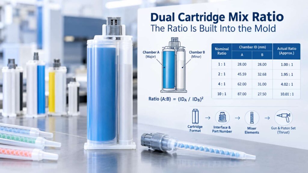
- A dual cartridge does not measure the mix ratio — it manufactures it. The ratio is fixed the moment the mold is cut, because both pistons share one stroke and the volume ratio equals the square of the chamber inner-diameter ratio.
- You can read the real ratio off the drawing: Ratio (A:B) = (ID_A / ID_B)². Published chamber IDs back-calculate to values very close to the nominal 1:1, 2:1, 4:1 or 10:1.
- In a 2:1, 4:1 or 10:1 system, the minor chamber dispensing more slowly than the major chamber is a design feature, not a fault. Only lead-lag, mid-stroke stall, or visible deformation warrant investigation.
- One mix-ratio input locks four hardware decisions: whether the format exists, which interface and part number to use, how many mixer elements you need, and what gun and piston set can deliver the thrust.
- Verify a ratio on the drawing and datasheet — not on the cured bead. A uniform color and a cured joint are supporting evidence, not a ratio verification.
A two component mix ratio cartridge looks like a container, but it is really a metering device. When a formulation sheet calls for a 10:1 mix ratio by volume, that number is not a setting you dial in at the gun — it is a physical dimension baked into the mold. The ratio you get is the ratio the two chamber diameters were cut to. This guide explains how a ratio specification becomes a hardware specification, how to read it off a cartridge drawing, which ratios actually exist in which capacities, and how the same input drives the mixer and the dispensing gun.
By the end you will be able to take any ratio from a technical data sheet and trace it through four connected hardware decisions — format availability, interface and part number, mixer element count, and thrust budget — and know which symptoms are normal and which point to a real fault.
Why a Mix Ratio Is a Mold Dimension, Not a Formulation Decision
The first move is to stop treating the mix ratio as a chemistry parameter. Chemistry decides what ratio the adhesive needs; the cartridge decides what ratio it delivers. Those are different problems, and the cartridge solves its half with geometry, not adjustment.
From Stoichiometry to Stroke: How a Ratio Becomes Geometry
A two-part adhesive is specified by a stoichiometric or volumetric ratio — resin to hardener, Part A to Part B. The cartridge cannot weigh or count molecules. What it can do is displace two fixed volumes of material through two sealed chambers using one driven piston plate. The hardware therefore converts a chemical requirement into a geometric one: the ratio of displaced volumes.
A dual cartridge does not measure the mix ratio — it manufactures it. The ratio is fixed the moment the mold is cut.
The Shared-Stroke Constraint: Why Both Pistons Travel the Same Distance
In a dual cartridge, both pistons are driven by the same plate, ram, or follower. They are mechanically linked, so they advance the same distance on every stroke. Because both chambers empty over the same travel, the volume each delivers is set only by its internal cross-sectional area:
Volume ratio (A:B) = cross-sectional area ratio (A:B) = (inner diameter A / inner diameter B)²
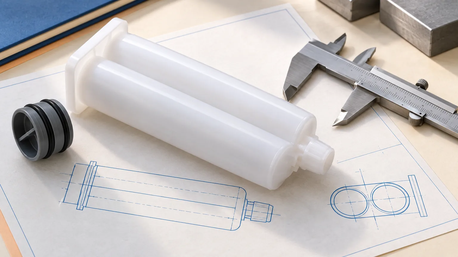
Two consequences follow directly. First, to change the ratio you change the chamber diameters, not the stroke — there is no “ratio adjustment” at the tool. Second, in any non-1:1 cartridge the two chambers must be the same length (a single tool has to push both to the bottom), so the entire ratio difference is carried in the diameters. That is why a 10:1 cartridge has one very large barrel and one visibly small one: the diameter split is the ratio.
Nominal Ratio vs. As-Molded Ratio: What the Label Does Not Tell You
Three numbers are easy to confuse: the ratio the formulation requires, the nominal ratio printed on the cartridge, and the ratio the molded part actually delivers. Molding shrinkage, chamber-wall tolerance, piston-seal compression, and central-wall deflection under pressure all move the third number relative to the second.
This is visible in the published data. For the C-system 400 ml 2:1 part, the listed chamber IDs (A 45.59 mm, B 32.68 mm) back-calculate to about 1.95:1 — close to, but not exactly, the nominal 2:1. The binding specification is the supplier’s stated ratio on the datasheet, confirmed against the drawing tolerance and inspection method, not the area ratio you derive by hand. Where a formulation is weighed rather than measured by volume, the density conversion between the two is covered separately in our guide on converting mix ratios between volume and weight.
The Area-Ratio Rule: How to Read a Cartridge Like a Drawing
The single most useful check you can run is also the simplest: take the chamber inner diameters from the drawing and square their ratio. This turns an abstract ratio into a number you can verify before any material is dispensed.
Volume Ratio Equals Cross-Sectional Area Ratio
Under the shared-stroke assumption — both chambers travel the same distance and empty completely — the displaced-volume ratio equals the internal cross-sectional-area ratio, which equals the square of the inner-diameter ratio:
Ratio (A:B) = (ID_A / ID_B)²
To reverse it, read ID_A and ID_B off the drawing, divide, and square. The result is the as-drawn ratio. Treat it as the geometric intent; confirm the binding value against the supplier’s datasheet and tolerance.
Worked Example: Back-Calculating the Ratio from Published Chamber IDs
Take a real C-system 200 ml 2:1 cartridge, part number C-CD200-21-PP-01-STD. The published chamber IDs are A = 38.70 mm and B = 27.38 mm.
(38.70 / 27.38)² = (1.413)² ≈ 1.997 ≈ 2.00
The cartridge reads as a 2:1 — exactly as labeled. Run the same check on a C-system 400 ml 10:1 part, C-CD400-101, with IDs A = 60.76 mm and B = 19.24 mm:
(60.76 / 19.24)² = (3.158)² ≈ 9.97 ≈ 10.0
Do this on the drawing before you do it on the bench. The full dimension set for every part is on the dual-component cartridge datasheet page, and 3D models in STEP/IGES are available from the request 3D models page for design-in work.
Why the Small Chamber Is Where Ratio Accuracy Is Won or Lost
Look at the volume shares the area rule produces:
| Nominal ratio | Volume share A : B | Area ratio (A:B) | Diameter relation (ID_A : ID_B) | What it means on the bench |
|---|---|---|---|---|
| 1:1 | 50.0% / 50.0% | 1.00 | 1.00 : 1 | Symmetric barrels, matched backpressure |
| 2:1 | 66.7% / 33.3% | 2.00 | 1.41 : 1 | Mild asymmetry, still visually balanced |
| 4:1 | 80.0% / 20.0% | 4.00 | 2.00 : 1 | Distinctly stepped barrel |
| 10:1 | 90.9% / 9.1% | 10.00 | 3.16 : 1 | Small chamber governs ratio accuracy |
In a 10:1 system the minor chamber holds only about 9% of the volume, yet any geometric error in that small chamber is amplified roughly tenfold into the final ratio. That is the mechanical reason wide-ratio cartridges depend on tighter wall rigidity and dimensional control: ratio accuracy lives in the small chamber.
Unequal A/B Output Is a Design Feature, Not a Dispensing Fault
This is the section to send to anyone who has watched a 10:1 cartridge and concluded the gun is broken. At a 2:1, 4:1 or 10:1 ratio, unequal output is the mechanism — not a symptom.
What “Even Dispensing” Actually Means at Each Ratio
In a non-1:1 system, unequal A/B output is not a symptom. It is the mechanism. If both sides discharged at the same rate, the ratio would be 1:1.
The two pistons move at the same linear speed, but the smaller chamber has the smaller cross-section, so its volume flow is lower by the area ratio. At 10:1 the minor side naturally advances far more slowly. Expecting equal output from a 10:1 cartridge is expecting it to disobey its own geometry.
The Three Symptoms That Do Warrant an Investigation
After establishing that slow minor-chamber output is normal, these are the patterns that are not explained by geometry:
- Timing anomaly — one side starts or stops noticeably later than the other (lead-lag), rather than simply advancing slower throughout.
- Drift during the stroke — the A/B relationship changes partway through a single cartridge, producing a bead that starts right and ends wrong.
- Physical anomaly — spitting or surging, visible backflow, or barrel deformation.
Each of these points to a different layer: trapped air or poor piston seating for timing, deformation or piston bypass for drift, and a tool or seal fault for physical signs. The guide to fixing uneven 2K adhesive dispensing walks through correction steps, and trapped air in 2K cartridges covers the start-up timing cause specifically.
Lead-Lag at Start-Up: Why the First Bead Is Always Off Ratio
Fresh pistons do not seat in perfect sync the instant a cartridge is loaded. Follow the part’s priming instruction — dispense until both chambers flow steadily — and discard the first length of incompletely mixed material before the mixer is considered live. Correct ratio in the mold does not mean correct ratio in the first few centimeters of bead; the two are separated by seating and priming.
| What you observe | At 1:1 | At 4:1 / 10:1 | Verdict |
|---|---|---|---|
| B-side advances visibly slower | Unusual | Expected | Normal — do not repair |
| Equal-looking output from both sides | Expected | Impossible by geometry | Suspicious — verify ratio |
| B-side starts late then catches up | Investigate | Investigate | Lead-lag, not geometry |
| B-side stalls mid-stroke | Investigate | Investigate | Air, seal or tool fault |
Decision 1 — Does This Ratio Exist in This Capacity?
The first hardware question a procurement engineer faces is simpler than it looks: is there a standard mold for this ratio in this capacity, or does the specification require custom tooling? The published product range answers it directly.
Standard Ratio × Capacity Combinations Across A / B / C / F Systems
The four interface systems serve different capacity and pressure bands: A and B cover small 50 ml manual and low-viscosity work, C covers 200–1500 ml threaded industrial mounting, and F covers 200–1500 ml high-pressure twist-lock use. Within those bands, the standard ratio coverage is:
| Mix ratio | A system (50 ml) | B system (50 / 100 ml) | C system (200–1500 ml) | F system (200–1500 ml) |
|---|---|---|---|---|
| 1:1 | Standard (50 ml) | Standard (50 & 100 ml) | Standard (200 / 400 / 600 / 1500 ml) | Standard (200 / 400 / 1500 ml) |
| 2:1 | Standard (50 ml) | Standard (50 ml) | Standard (200 / 400 / 450 ml) | Standard (200 / 400 ml) |
| 4:1 | Standard (50 ml) | Standard (50 ml) | Standard (400 ml) | Standard (400 ml) |
| 10:1 | — | — | Standard (400 ml) | Standard (200 / 400 ml) |
Two patterns hold across the catalog. As capacity grows, the number of available ratios tends to narrow; as the ratio becomes more asymmetric (4:1, 10:1), the available capacity band narrows. That is why a 10:1 specification usually lands on a 400 ml C- or F-system cartridge, while 1:1 spans the full range. The complete list of two-component cartridges in 50ml, 200ml and 400ml is on the product page, with chamber IDs for every part number.
The Combinations That Require Custom Tooling

Standard molds cover the common ratios — 1:1, 2:1, 4:1 and 10:1 — across the capacities above. A specification outside that grid needs custom tooling: an off-grid ratio such as 3:1, 5:1 or 8:1, a non-standard capacity, a private interface, or a keyed anti-misassembly feature. This is a normal product decision, not a limitation, and the custom cartridge tooling program exists for exactly these cases.
Choosing Between a Larger Capacity and a Custom Mold
When the exact ratio × capacity combination is not standard, decide with three questions:
- Can total volume be absorbed by the nearest standard capacity?
- Does the ratio fall on a standard step (1:1 / 2:1 / 4:1 / 10:1)?
- Is the field tooling willing to change once to match a different format?
Change the ratio and you change the mold. Change the capacity and you change the tooling around it — the second is usually cheaper. Capacity trade-offs between the two most common sizes are covered in the 200ml vs 400ml dual cartridges comparison and the broader adhesive cartridge sizes and materials guide, while cartridge sizing and material compatibility handles chemistry-driven material choice.
Decision 2 — Interface and Part Number: How the Ratio Is Encoded
Once the ratio and capacity are fixed, the part number already encodes both — and the physical interface is what stops the wrong mixer from being assembled.
Why the Same Capacity Has Different Outlet Geometries
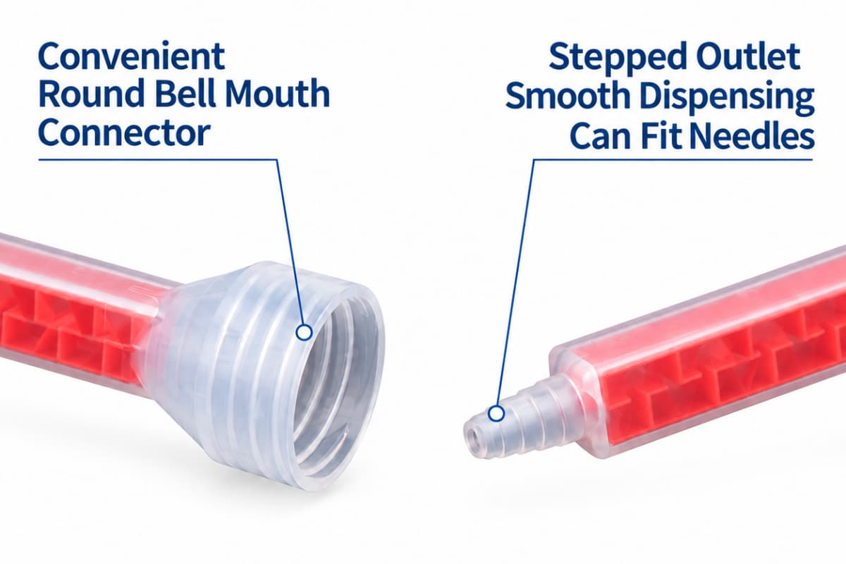
The outlet interface is chosen by backpressure and dispensing method, not by capacity alone. Small 50 ml manual and low-viscosity formats use bayonet or snap-lock outlets; larger 200–400 ml high-viscosity industrial formats use threaded or high-pressure twist-lock outlets. The four A, B, C and F interface systems are described in detail on the connection-types page; the ratio-to-interface link is that wide ratios generate a differential backpressure the interface must contain.
Reading Ratio and System From the Part Number
A Haijing dual-cartridge part number carries the system, capacity, and ratio as distinct fields. In C-CD200-21-PP-01-STD, “C” is the interface system, “200” is the capacity in ml, “21” is the 2:1 ratio, “PP” is the material, and the trailing fields are variant and finish. The ratio field is what lets you confirm the ratio from the code alone: “11” = 1:1, “21” = 2:1, “41” = 4:1, “101” = 10:1. A C-CD400-101-PBT-01-STD is therefore a C-system, 400 ml, 10:1 part in PBT — no drawing required to read the ratio class.
The Interlock Question: Can the Wrong Mixer Physically Fit?
Often yes, and that is the danger. A mixer that seats on the outlet may still be built for the wrong ratio or a different interface family, so it fits physically but fails chemically. That is why keyed and interlock outlets exist: they convert a possible human error into a physical impossibility. The mixer interchangeability guide by cartridge system shows which nozzles actually cross-fit. A mixer that fits is not a mixer that matches.
Decision 3 — Mixer Geometry: Why Asymmetric Ratios Need More Elements
The cartridge sets the ratio; the static mixer only blends it. But the ratio it must blend decides how much folding the mixer needs. The static mixing nozzle engineering guide covers geometry selection in full — here the focus is the ratio correction.
Element Count by Ratio: The Starting Ranges
In a 10:1 system the hardener enters the mixer as a thin ribbon beside a much wider resin stream. Every element splits that ribbon again. Stop folding too early and pockets of pure hardener reach the nozzle. The starting element-count ranges below reflect general industry catalog bands and the site’s own published guidance; the exact count depends on viscosity and chemistry and should be confirmed against the adhesive technical data sheet. For a full method, see how many mixing elements you actually need.
| Mix ratio | Typical element count (starting range) | Why | If undersized |
|---|---|---|---|
| 1:1 | ~7–16 | Two equal streams fold symmetrically | Rarely under-mixed |
| 2:1 | ~10–18 | Mild asymmetry | Slight streaking |
| 4:1 | ~18–24 | Minor stream must be distributed | Streaks in bead center |
| 10:1 | ~24–32+ | Minor stream is under 10% of volume | Uncured pockets, tacky spots |
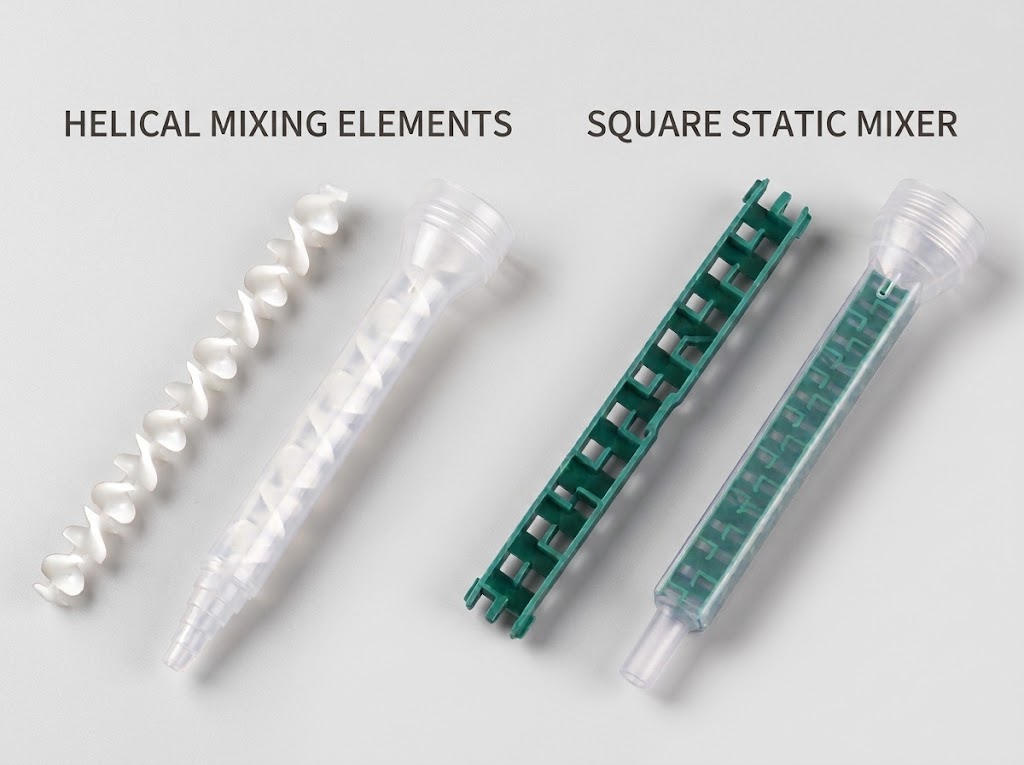
Helical, Quadro and Square: Which Geometry Suits Wide Ratios
Geometry choice tracks the ratio and viscosity. Wide ratios and high filler loads benefit from higher-shear square (Quadro) elements that achieve homogeneity in a shorter housing; low ratios and medium-to-low viscosities tolerate gentler helical elements. The trade is pressure drop: square elements shear harder and need stable pneumatic pressure, while helical elements suit manual guns. The detailed geometry comparison belongs in the engineering guide; the point for ratio selection is that wider ratios push toward more aggressive geometry, not just more elements.
Ratio, Viscosity and Mixer Length: The Two Corrections That Stack
Two corrections add up. The ratio correction (wider ratio needs more elements) stacks with the viscosity correction (higher viscosity needs more elements). Both can also require a longer or wider mixer, not just more elements. When a bead shows color streaks or uneven cure, add elements first, then consider a different geometry, and only then consider a dynamic mixer — each step costs more than the last. Temperature matters too: a cold adhesive is more viscous, so confirm material temperature before blaming the mixer. For materials beyond static mixing, the static and dynamic mixers overview explains where a rotating element becomes necessary.
Decision 4 — Gun, Piston Set and the Thrust Budget
The ratio also reaches the tool. The question is not whether a gun “supports” a ratio, but whether its piston and follower hardware matches the cartridge geometry. The cartridge-format and dispensing-gun selection guide covers drive types; the ratio-specific points follow.
Matching the Ratio to the Plunger and Push-Disk Configuration
A common assumption is that a 1:1 gun would “force equal stroke” on a 10:1 cartridge. That is inaccurate — every dual-cartridge gun already drives both pistons the same distance. What actually goes wrong is a mismatch between the gun’s follower, push disks, or adapter plate and the cartridge’s chamber layout. The dual-cartridge epoxy gun guide shows the matched hardware per ratio and size. A cartridge that physically fits into a gun does not prove the metering setup is correct.
What Changes at 4:1 and 10:1: Pressure, Wall Rigidity and Piston Tracking
Wide ratios create a backpressure difference across the central wall: the large chamber pushes harder than the small one. That differential loads the wall and tests piston tracking. Because, as shown in Section 2.3, ratio accuracy lives in the small chamber, wide-ratio cartridges demand tighter wall rigidity and more consistent piston follow — exactly the failure modes examined in the 2K cartridge failure analysis guide. Select tooling that holds the follower square to both chambers rather than squeezing the major side.
Manual, Pneumatic or Battery: Choosing by Shot Volume and Force
Decide the drive by three variables: shot volume per dispense, cartridges per hour, and the cost of one bad joint. Manual guns suit low-volume, fine work; pneumatic and battery guns suit high-throughput or high-viscosity lines where consistent force matters more than hand effort. No single thrust number applies across adhesives — confirm against the specific material and cartridge size in the gun guide above.
How to Verify a Cartridge Is Actually On Ratio Before You Approve It
For a brand owner or OEM buyer, the article ends where qualification begins: proving a lot is on ratio before it enters production.
A Three-Level Verification Sequence
- Mechanical layer — confirm the ratio configuration matches the cartridge geometry; pistons and follower plates are seated; no visible deformation or leakage.
- Dispense layer — both chambers start cleanly, no abnormal lag, steady output, no backflow or barrel swell.
- Ratio layer — measure dispensed A and B volumes and compare to the specified ratio, stating explicitly whether the specification is by volume or by weight.
Uniform color and the fact that the adhesive cures are supporting evidence. Neither is a ratio verification.
Sample Qualification Criteria for OEM Buyers
When evaluating samples, request or test: the drawing dimension fields (IDs, length, tolerance), chamber-to-chamber consistency across the lot, piston-seal consistency, cavity-venting method, and label and batch traceability. Confirm the supplier’s stated ratio and its tolerance from the datasheet rather than inferring it from appearance. Sample kits and qualification support are available through the submit your ratio and capacity requirements channel.
What a Drawings-and-Datasheet Review Should Cover
The review checklist is short but non-negotiable: inner diameters and their tolerances, length consistency across both chambers, central-wall structure, outlet geometry, material grade, and a traceable batch number. Approve the drawing, not the sample you happened to receive. The dual-component cartridge datasheet and request 3D models (STEP/IGES) pages provide the source documents; pair them with the full dual-component cartridge range when specifying a program.
Troubleshooting Triage: Which Layer Owns the Symptom?
When something looks wrong, route it to the layer that owns it before changing hardware. This table is a triage map, not a repair procedure — each row points to the page that covers the fix.
| Symptom | Layer that owns it | Route |
|---|---|---|
| Bead streaky / marbled | Mixer geometry & element count | → element count guide |
| Bead cures partly, tacky spots | Off-ratio or under-mixed | → fixing uneven 2K adhesive dispensing |
| One side starts late | Air / piston seating / lead-lag | → trapped air in 2K cartridges |
| Output changes mid-cartridge | Cartridge deformation, piston bypass | → 2K cartridge failure analysis |
| Very hard trigger, ratchet slip | Thrust, cold material, oversized mixer | → dispensing gun guide |
| Drip / run-on after release | Residual pressure, not a seal fault | → back pressure and off-ratio beads |
| Everything looks right but ratio unverified | Verification, not hardware | → Section 8 of this guide |
What This Guide Does Not Cover (And Where to Go Instead)
To keep this reference precise, several adjacent topics are handled on their own pages:
- Volume-to-weight density conversion — converting mix ratios between volume and weight
- Capacity and material selection — cartridge sizing and material compatibility
- Mixer element-count method — how many mixing elements you actually need
- Interface and interchangeability — mixer interchangeability by cartridge system
- Filling both chambers correctly — cartridge filling machine selection guide
Frequently Asked Questions
Does the cartridge or the static mixer set the mix ratio?
The cartridge sets it; the mixer only blends the two streams the cartridge has already metered. A wrong mixer under-mixes, but it cannot change the ratio the cartridge delivers.
How do I calculate the mix ratio from the chamber diameters?
Use Ratio (A:B) = (ID_A / ID_B)², with both pistons sharing one stroke. The result is the as-drawn ratio; confirm the binding value against the supplier’s datasheet and tolerance, because molding and chamber-wall effects shift the as-molded ratio slightly.
Is a 2:1 volume ratio the same as a 2:1 weight ratio?
No. Volume ratio and weight ratio differ whenever the two components have different densities. The conversion depends on the specific gravity of each part and is worked through in the volume-to-weight guide.
Why does one side of my dual cartridge dispense faster?
At 2:1, 4:1 or 10:1 the major chamber has the larger cross-section, so it delivers more volume per stroke — by design. Only lead-lag, mid-stroke stall, or visible deformation are real faults; steady slower minor-chamber output is normal.
Can I use a 4:1 static mixer on a 10:1 cartridge?
It may seat, but a 4:1 mixer has fewer elements than a 10:1 system needs, so the hardener ribbon is not fully distributed and the bead can cure unevenly. Select the mixer element count and geometry for the actual cartridge ratio.
Can a 1:1 dispensing gun dispense a 10:1 cartridge?
The stroke is the same either way — both pistons always travel together. What matters is whether the gun’s follower, push disks, and adapter match the 10:1 chamber layout. “Fits in the gun” is not proof the metering is correct.
Which mix ratios are available in 400ml dual cartridges?
Across the standard range, 400 ml cartridges cover 1:1, 2:1, 4:1 and 10:1 in the C and F systems (see the availability matrix in Section 4). A ratio outside that set requires custom tooling.
What happens if the mix ratio is off in a 2K cartridge?
An off ratio leaves the adhesive under-cured or tacky, lowers bond strength, and produces uneven cure across the bead. Verify the ratio from the drawing and dispense volumes before replacing equipment — most “ratio” problems are geometry or seating issues, not the gun.
Is a small deviation in mix ratio acceptable?
That is set by the adhesive formulation, not by the cartridge. The acceptable tolerance comes from the formulation supplier’s technical data sheet; confirm it and measure the actual A/B output against it during qualification.
Do both pistons always travel the same distance?
Yes. They are driven by one plate or follower, so the shared stroke is what lets a single tool meter a dual cartridge. The ratio difference is carried entirely in the chamber diameters, which is why non-1:1 cartridges have unequal barrel sizes.
From Ratio to the Hardware That Actually Delivers It
The ratio on your formulation sheet doesn’t stay a chemistry number for long. Within a few steps it turns into a chamber diameter, a part number, a mixer geometry and a thrust budget — and each of those has to agree with the others. Where it goes from here mostly depends on which end of the supply chain you’re standing at.
If you’re specifying cartridges for a product, the open questions usually come down to three numbers: the mix ratio, the fill volume, and the chemical family. Send those over and we’ll tell you straight whether a standard mold already covers it or whether custom tooling is worth the detour — and put a ratio-verified sample kit in your lab’s hands so you can qualify it before anything goes into production. The custom cartridge tooling page shows what’s on the table, and the contact form is the quickest way to open that conversation.
If you’re on the dispensing end, the same three inputs — ratio, viscosity, and the bead width you’re aiming for — are what decide whether your current gun and mixer actually line up with the chamber geometry above. Share them and we’ll come back with a configuration that fits; or, if you’d rather work through it yourself first, the cartridge-format and dispensing-gun selection guide lays out the trade-offs in full.
One thing this whole ratio conversation tends to leave out: a correct ratio in the mold is not the same as a correct fill in the chamber. Once the cartridge side checks out, the cartridge filling machine selection guide is where the other half of that qualification lives.