Air Pockets in 2K Cartridges: How Trapped Air Ruins Mixing Ratios and Precision Dispensing
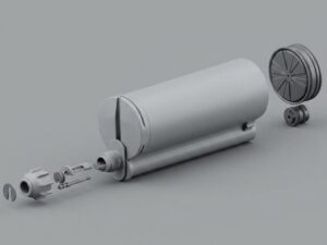
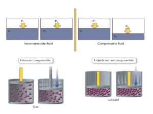
The dispenser applies a constant forward force to the piston. For Part A, which is an incompressible liquid, output is immediate and fully volumetric. For Part B, however, any trapped air pocket compresses first upon piston advance, absorbing energy and temporarily stalling liquid delivery; the compressed air then releases its stored energy only after sufficient pressure builds. As a result, the volumetric outputs of the two components become mismatched, breaking the intended mix ratio and causing Part A to be over delivered relative to Part B at the dispensing tip.
The Anatomy of Dispensing Failures: Why Air Pockets in 2K Cartridges Are Costlier Than You Think
| Metric | Single-Component (1K) | Dual-Component (2K) |
|---|---|---|
| Failure Manifestation | Physical bead gap | Chemical under-cure / soft spots |
| Detection Method | Visual optical inspection | Destructive shear test / thermal analysis |
| Rework Requirement | Bridging / gap re-fill | Full joint teardown & solvent stripping |
When an operator or a Cartesian dispensing robot purges a dual component system, forward drive pressure is applied across both chambers simultaneously. If one chamber contains trapped air pockets while the other is fully saturated with incompressible resin, the piston motion no longer produces balanced fluid output. Instead of maintaining a precise volumetric ratio—such as 1:1, 2:1, 4:1, or 10:1—the liquid in the void-free cylinder moves ahead, while the air in the companion barrel absorbs the mechanical displacement.
The consequences compound down the line:
-
Off-Ratio Joint Weakness: Sub-stoichiometric polymer chains fail to reach design glass transition temperatures ($T_g$) and target tensile strength.
-
Component Surface Contamination: Dropping, weeping, and pressure spitting discharge unmixed hardener or resin onto critical peripheral parts.
-
Production Rework & Scrap: Defective assemblies may initially seem intact during assembly, only to fail later during thermal cycling or mechanical load testing.
How Air Pockets Disrupt Volumetric Stoichiometry and Static Mixing
Compressibility Mismatch: Liquid Adhesive vs. Trapped Gas
where K denotes the bulk modulus of the medium. The bulk modulus of air is several orders of magnitude lower than that of polymer‑based resins.
PRESSURE EQUALIZATION & ENERGY RELEASE IN A 2K SYSTEM
PHASE 1 – DIVERGENT FLOW (Trigger Depressed)
| Chamber | State |
|---|---|
| A (Pure Resin) | High pressure → Dynamic fluid flow |
| B (Air Pocket) | Energy storage → Stagnant fluid flow |
Result at Mixer Nozzle:
-
Element 1: Resin‑rich, hardener‑starved → Output is off‑ratio.
PHASE 2 – UNCONTROLLED DISCHARGE (Trigger Released)
| Chamber | State |
|---|---|
| A (Pure Resin) | Piston stops → Zero dynamic flow |
| B (Compressed Air) | Air expands → Forces hardener outward |
Result at Mixer Nozzle Tip:
-
Post‑cycle weeping, drooling, and spitting onto substrates.
Off-Ratio Dispensing and Incomplete Polymer Cross-Linking
-
Localized sticky or tacky spots that remain unsolidified indefinitely.
-
Micro-porosity within the cured matrix, causing stress concentrations under mechanical fatigue.
-
Reduced chemical and moisture resistance along the bond interface.
Troubleshooting Checklist: Identifying Symptoms Caused by Trapped Air
| Visual Symptom | Root Mechanical Cause | Verification Method | Immediate Remedial Action |
| Puffing or Spitting at Tip | Pressurized air bubble passing through static mixer elements and expanding at ambient outlet. | Collect purge shot in transparent cup; observe audible popping or broken output streams. | Purge system; verify whether bubble repeats or clears. Inspect lot for packaging headspace. |
| Nozzle Drooling After Trigger Release | Compressed air inside barrel acting as a mechanical spring, continuing to push fluid forward. | Release trigger on a pneumatic dispensing gun; observe whether nozzle discharge halts cleanly within 0.5 seconds. | Relieve backpressure; inspect cartridge rear pistons for air trapped behind or within the wiper lips. |
| Periodic Soft Spots Along Joint | Intermittent micro-bubbles in one barrel cylinder disrupting the volumetric mix ratio. | Perform durometer hardness testing (Shore D/A) at 50 mm intervals along the cured bond line. | Check filling line degassing records; confirm balanced piston insertion depths across A and B barrels. |
| Uneven Plunger Travel | Unequal resistance caused by compressing air pockets against high fluid viscosity. | Visually monitor side-by-side push-rod alignment during powered forward stroke. | Stop dispensing; check cartridge wall for visible internal voids or piston tilt inside the chamber. |
Where Do the Bubbles Come From? Cartridge Design vs. Packaging Process
SOURCES OF AIR ENTRAINMENT IN 2K SYSTEMS
-
Material Degassing Deficiencies
Micro‑bubbles suspended in formulation prior to fill
— Caused by vacuum failure during blend/pump. -
Bottom‑Up Filling & Clearance Errors
Bottom pocket formed if lance does not stay submerged
— Caused by nozzle pulling up faster than fluid. -
Piston Insertion & Sealing Failures
Air column trapped between liquid surface and piston lip
— Caused by solid piston pushing air down. -
Barrel Wall Flexure Under Pressure
Fluid/Air blow‑by around wiper seal during dispensing
— Caused by thin walls expanding under 6 bar.
Filling and Venting Defects: Plunger Insertion and Trapped Pockets
-
Filling from the Bottom Up: The dosing nozzle must enter the bottom of the cartridge barrel and retract in sync with the rising fluid level. If the nozzle withdraws faster than the fluid enters, an air pocket is trapped at the base.
-
Piston Insertion Mechanics: Once filled from the rear, pistons must be inserted into the cylinders. A standard solid piston acts as an airtight plug; pushing it directly into a filled barrel traps an air column between the liquid surface and the piston seal.
| Feature | Solid Piston (High Risk) | Air‑Bleed Piston (Safe) |
|---|---|---|
| Vent | None | Open central vent |
| Air behaviour | Trapped and compressed | Escapes freely |
| Fluid surface | Sealed (plug) | Open to vent |
| Primary risk | Air entrainment, pressure surge | Minimised |
Barrel Tolerances and Piston Seal Integrity Under High Backpressure
-
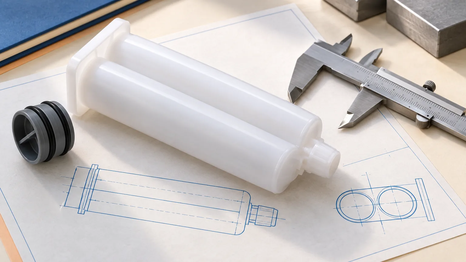
Barrel Wall Deflection: When dispensing highly filled structural adhesives, internal hydraulic pressures can exceed 6 bar. Thin-walled, low-grade plastic cylinders flex and bow outward under load. This barrel expansion compromises the seal between the piston wiper lip and the cylinder wall, allowing air to leak backward or forward past the piston.
-
Dual-Lip Wiper Geometry: Low-cost single-wiper pistons often twist slightly off-axis under load. Precision dual-wiper pistons maintain two continuous contact rings against the inner cylinder wall, scraping the tube clean and preventing fluid blow-by or air siphonage.
Preventing Air Entrainment: Engineering Features to Demand from Your Cartridge Manufacturer
CRITICAL SEALING INTERFACES ON A 2K CARTRIDGE BARREL
-
Outlet Manifold Interface (Hermetic Cap Seal)
-
Located at the top (outlet) end of the barrel.
-
Provides a hermetic seal to prevent leakage and contamination at the manifold connection.
-
-
Rigid Outer Reinforcement
-
Surrounds the barrel wall externally.
-
Designed with ribs to resist hoop stress caused by internal pressure.
-
-
Consistent Cylinder Wall Thickness
-
Maintains uniform wall thickness along the entire barrel length.
-
Zero internal taper ensures consistent volume and smooth piston travel.
-
-
Ultra‑Smooth Inner Surface (Ra)
-
The internal bore surface has a low surface roughness (Ra value).
-
Prevents micro‑channeling (leak paths) along the sealing interfaces.
-
-
Dual‑Lip Piston with Elastomeric Air‑Release Vent
-
Located at the bottom (plunger) end.
-
Features two sealing lips for reliable double sealing.
-
Incorporates an elastomeric vent that allows trapped air to escape during filling or dispensing, reducing air entrainment risk.
-
| Engineering Feature | Technical Requirement | Operational Function | Sourcing Assessment Criterion |
| Barrel Wall Rigidity | High-modulus polypropylene (PP) or polybutylene terephthalate (PBT) polymers | Prevents outward barrel deformation under high dynamic push-rod pressure. | Request wall thickness specs and burst pressure ratings. |
| Bore Concentricity & Cylindricity | Strict mold core tolerances with minimal internal draft angle | Eliminates gaps between the piston wiper and barrel wall along the entire stroke. | Inspect dimensional drawing tolerances for inner diameters. |
| Piston Venting System | Integrated valve plug or self-venting elastomeric membrane | Allows complete evacuation of head-space air during mechanical piston insertion. | Confirm compatibility with automatic vacuum or mechanical plunge tools. |
| Surface Finish (Ra) | Mirror-finish internal mold polish | Prevents micro-grooving where air pockets cling to barrel walls during resin filling. | Verify high-precision injection tooling quality standards. |
| Manifold Separation Wall | Robust isolation barrier at outlet neck | Prevents cross-contamination and interfacial air bleeding prior to the mixer attachment. | Check manifold closure design (retaining nut vs. integrated twist-lock). |
Best Practices to Eliminate Air Bubbles Before and During Production
Shop-Floor Operating Procedure
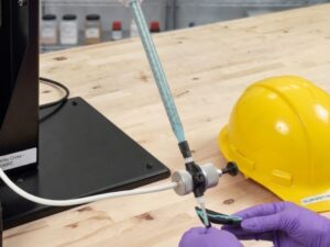
The standard pre dispense fluid balancing sequence begins with storing and standing the cartridge upright (outlets facing upward) prior to use. Next, remove the transport cap and visually inspect both fluid outlet ports to confirm that they are filled to a level and even condition. Then, without a mixer attached, slowly advance the drive rods until both Part A and Part B emerge cleanly and simultaneously from the manifold. Finally, mount the static mixer and dispense a waste bead equal to the length of the mixer; verify that the dispensed material exhibits uniform visual appearance and shows no signs of popping or air release before applying it to the actual product.
-
Vertical De-aeration Resting: Store cartridges vertically with the dispensing nose oriented upward whenever formulation viscosity allows. This causes entrained macro-bubbles to migrate toward the manifold outlet rather than remain suspended along the cylinder stroke.
-
Pre-Dispense Fluid Leveling (Bleeding): Never attach a static mixer directly to a newly loaded 2K cartridge and immediately apply adhesive to the workpiece. Piston depths may vary slightly after storage. Place the cartridge into the manual dispensing gun or pneumatic system without a mixer attached, and pull the trigger until both materials emerge evenly at the exit ports.
-
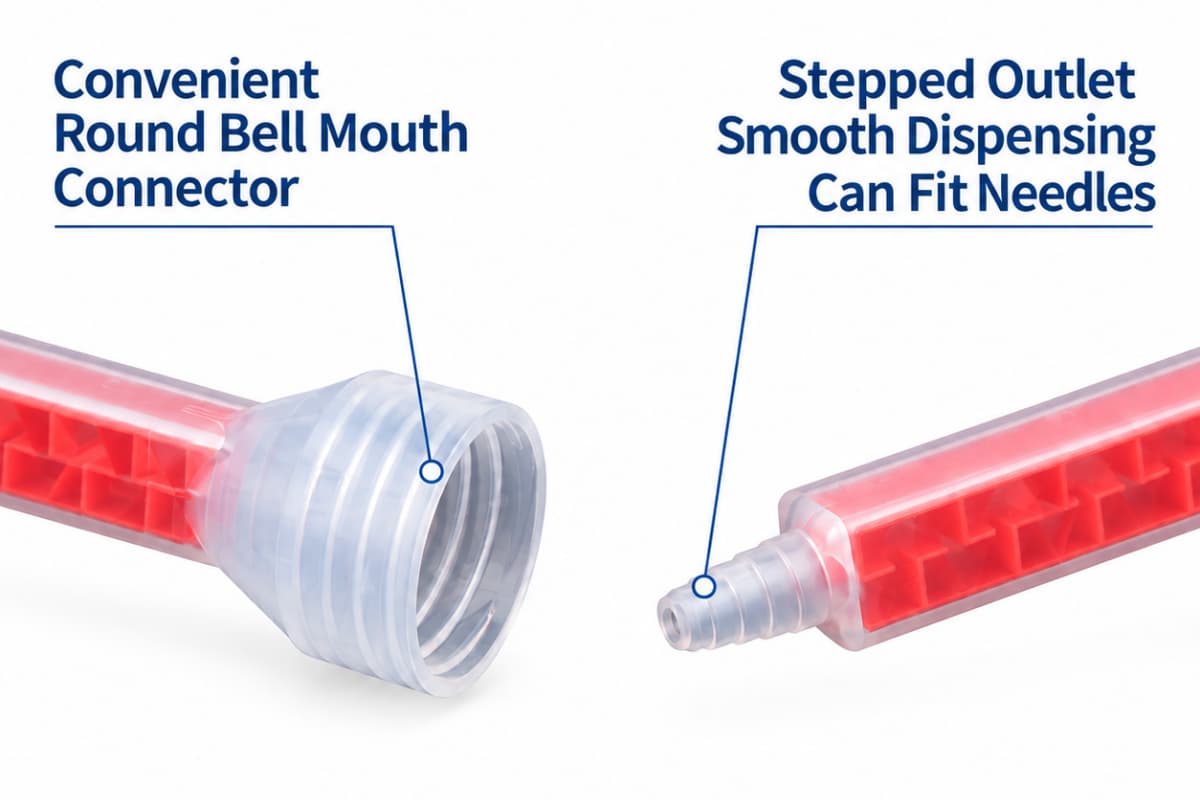
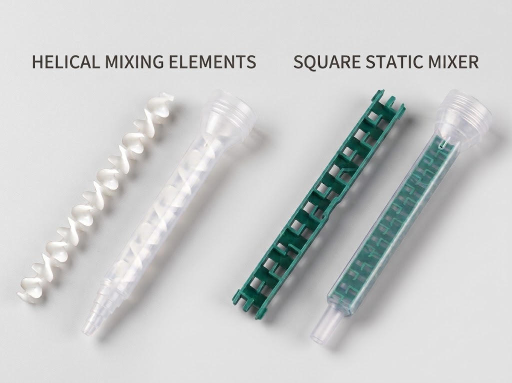
Purge the First Mixer Volume: Once the mixer is locked into place, dispense and discard an initial waste shot equal to at least one to two times the internal volume of the mixer tube. This purges ambient air trapped within the baffle tree elements and confirms balanced forward flow.
-
Matched Pneumatic Pressures: When running pneumatic lines, match air pressure to material viscosity. Pressures set too high can compress trapped pockets violently, causing blow-outs and severe sputtering, while pressures set too low may fail to drive high-viscosity materials through the mixer elements uniformly.
Key Takeaways
-
Volumetric Disruption: Air is a compressible gas, whereas industrial resins are hydraulic liquids. Trapped air pockets in a 2K adhesive cartridge absorb mechanical stroke displacement, breaking volumetric stoichiometry and causing unhardened soft spots.
-
Costly Line Downtime: Air pockets cause drooling, nozzle spitting, bead gaps, and premature joint failure, making void control a critical process variable rather than a minor cosmetic issue.
-
Component-Level Prevention: Packaging requires matched bottom-up filling along with air-bleed pistons that exhaust headspace gas during plunger insertion.
-
Hardware Rigidity: Low-tolerance cartridges expand radially under dispensing pressure, causing fluid blow-by and air induction around piston seals. High-rigidity walls and dual-wiper configurations are necessary for consistent delivery.
-
Process Discipline: Simple shop-floor steps—vertical staging, manual manifold pre-leveling, and discarding an initial mixer waste shot—eliminate a significant percentage of air-related dispensing defects.