Before comparing valve types, ask whether the device meters the material or only opens and closes it. Time-pressure, auger, piston and jet meter: each decides how much leaves, by a different mechanism. Diaphragm, needle, pinch, spool and poppet switch — they start and stop a flow whose volume something else already set. Separate metering from switching, then pressure-commanded from displacement-commanded, and four families cover almost every adhesive, sealant and potting job in production.
The short answer
- Low viscosity, wide bead tolerance, low capital cost → time-pressure. Cheapest to buy, nothing wetted to wear, but it cannot hold a tight shot across a shift.
- Filled paste, solder paste, thermally conductive → auger. Volume tracks screw revolutions, so upstream pressure stops mattering.
- Volume is the spec and viscosity moves → piston. A fixed chamber gives the same volume per stroke whatever the material does.
- Speed or non-planar surfaces → jet. No Z move, no contact, cycle time set by valve frequency.
Two questions sort every valve on the market
Two questions split the catalogue: whether the device measures, then what it measures.
Metering or switching. A metering valve produces a defined volume. A switching valve produces a defined state — open or closed — and the volume follows from pressure, time and whatever sits upstream. Both are sold as “dispensing valves”; only one knows how much it released.
Condition or volume. Within the metering half, one group commands the cause of flow — pressure applied for a duration — and infers the result. The other commands the result directly: a screw turning a set number of degrees, a piston sweeping a fixed chamber, a ball launching one drop. Precision is bought with wetted parts that wear.
pressure, time, stroke
screw turns, chamber swept, drop fired
decides how much
only starts and stops
Most published lists of “types of dispensing valves” sit in the bottom-left cell. The Dymax infographic covers pinch, spool, diaphragm, needle and poppet — all shut-off devices. Read it expecting a metering comparison and you buy a valve that cannot do what you measured in the trial.
The four metering families at a glance
Table 1. Four metering families compared on the variables that change a process
Ratings describe typical behaviour, not a specification. A specific model can sit outside its family’s usual range; the drawing and the vendor data sheet govern.
| Family | Meters by | Viscosity it handles well | Shot repeatability | Cycle | Signature failure |
|---|---|---|---|---|---|
| Time-pressure | Air pressure held for a set time | Low to medium, unfilled | Moderate; drifts within a shift | Medium | Dot size walks from first hour to last |
| Auger | Screw revolutions through a chamber | Medium to high, filled pastes | High | Medium | Dots shrink at high rate; slow wear drift |
| Piston | Fixed chamber swept per stroke | Low to high, viscosity-stable | Very high | Medium; limited by refill | Short or missing shots when refill lags |
| Jet | One drop launched per actuation | Low to medium; narrow rheology window | High | Very high | Off-centre drops, satellites, nozzle wetting |
Time-pressure: a command, not a volume
The valve is a needle over a seat. Air pressure is applied to the material column for a set time, the needle lifts, material flows through the bore, the needle closes. Volume is the integral of flow over that time, and flow through a restriction depends on the pressure difference, the viscosity and the bore. The controller sets the first and the duration; the other two are free to move while the recipe sits untouched.
Three drifts stack over a shift and do not cancel. The column above the needle falls as the reservoir empties, so the static head that adds to driving pressure falls with it. The material warms and flows more freely at the same pressure. The bore narrows as material cures at the tip, pushing flow the other way. The IMAPS review adds a fourth: with no seal at the needle end, residual back pressure drips after the pulse.
It survives for structural reasons: nothing in the wetted path moves, so it cleans fastest and each station can carry its own valve for the price of one auger. On a generous bead spec the tolerance band absorbs drift; on a bond that is invisible after assembly, it needs a measured first-off and an interval check.
What it cannot do. Hold a tight shot while reservoir level, temperature and tip condition all change. If your acceptance window is narrower than a few percent, it is being asked to control variables it cannot see.
Auger: volume per revolution
An auger puts a screw inside the fluid chamber and drives it with a motor. Each revolution carries a fixed volume forward, so the dose depends on rotation count rather than pressure. Change the supply pressure and the shot holds; change the temperature and it largely holds, because the screw displaces material instead of letting it escape.
That independence made auger the default for solder paste, thermally conductive compounds and other filled materials — and the family most often bought by people already burned by drift. The trade is in the wetted mechanism: screw and barrel sleeve run at a tight clearance, abrasive filler attacks it, and volume falls over months rather than minutes. Suck-back is weak, so tailing is usually handled by a small reverse rotation at the end of the shot — a practice one integrator describes. At high rates a screw can outrun its refill and starve, showing up as dots that shrink only on the fastest programs.
Piston: volume per stroke
A piston valve fills a chamber of known volume, seals it, and sweeps it. What leaves is the chamber volume, provided the chamber actually filled — independence from viscosity by design, and the strongest repeatability of the four.
The constraints follow. The chamber must refill between shots, so throughput is bounded by a fill stroke as well as a dispense stroke, and long continuous beads are out. An industry review of dispense pumps puts the second limit plainly: positive displacement suits Newtonian fluids and struggles with shear-thinning ones, because the chamber does not fill the same way twice.
So the failure to watch is not drift but incomplete fill — short shots, missing shots, a chamber that ingested air because refill time was set by cycle pressure rather than by the material. Check refill time and seal condition before dispense parameters.
Jet: a drop, not a bead
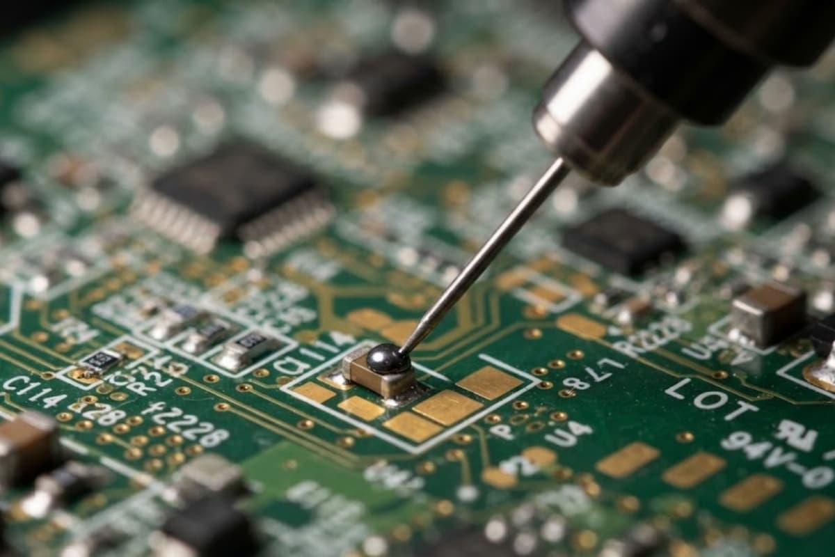
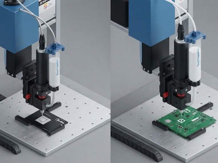
A jet fires material across an air gap instead of laying it down in contact. A ball or needle strikes a seat and the impact launches a droplet; the nozzle never touches the part. Removing contact removes the Z move, which is where most contact-process cycle time goes, so throughput follows valve actuation rather than gantry travel — the trade the desktop dispensing robot guide covers from the motion side.
Actuation speed is where vendor numbers need care. Pneumatic jets run in the low hundreds of hertz; industry reviews cite 200–300 Hz for pneumatic and around 600 Hz for piezoelectric. Current piezo products go further — the Nordson EFD PICO Pµlse to 1,000 Hz continuous, bursts to 1,500 Hz, 0.5 nL deposits; the Vermes MDS 3200 to 3,000 Hz at about 1 nL. Those are manufacturers’ figures on their own media: ceilings, not the rate you will hold on your adhesive.
What the family will not forgive is the material. A jet needs a rheology window: enough body to form a drop, not so much that it will not leave the nozzle. Particles above a fraction of the orifice block it, so filtration and deaeration become precondition. With no mechanical suck-back, tailing is set by the actuation profile, so the window is narrow and unforgiving of a material change.
The shut-off valves are not the alternatives
Diaphragm, needle, pinch, spool and poppet solve a different problem: stopping flow cleanly and quickly, without dripping or stringing. They are right when the volume is already set upstream — by a pump, a pressurised reservoir or a piston — and the valve only has to release it at the right moment.
Their advantage is suck-back: retracting material at close so the tail breaks cleanly, which is why needle and diaphragm designs dominate low-viscosity, high-cycle work. Their limitation is that they compensate for nothing — if upstream pressure sags, the deposit shrinks and the valve has no opinion.
So the framing is not “which of these nine types is best”. This group decides how cleanly flow stops; the four metering families decide how much flows. A system needs both answers, chosen separately.
Three axes that decide it, not a brochure
Viscosity alone is a weak selector: two materials at the same viscosity can demand different valves once tolerance and cycle time enter.
Bands are starting points for a supplier conversation, not specifications. 30,000 mPa·s at ±2% and 0.4 s is a different purchase from the same material at ±10% and 2 s.
A generous tolerance absorbs a metering family’s drift; a tight one rules the family out. A short cycle rules out anything waiting for a chamber to refill. Read the three rows together and most of the catalogue falls away.
One family controls the cause of flow and lets the volume follow. The other controls the volume and pays for it in wetted parts that wear.— the trade behind most valve specifications
Failure signatures, by family
Deposit defects look alike on a bench and differ by family once you know what each mechanism cannot do. Read the symptom, then inspect the component that mechanism depends on.
Table 2. Symptom to cause, by metering family
This table is about the valve. Before replacing it, confirm the defect is not coming from the cartridge, mixer or tip — that check is the next section.
| Family | What the operator sees | Mechanism behind it | Check this first |
|---|---|---|---|
| Time-pressure | First dots on size, last dots small; changes when the room warms | Static head falls with reservoir level; viscosity moves with temperature; bore narrows at the tip | Reservoir level at the time of the bad shot, material temperature, tip condition |
| Auger | Dots shrink only on the fastest program; slow downward trend over months | Screw outruns refill at high rate; screw-to-barrel clearance opens as filler abrades it | Refill pressure and time at that cycle rate; measured screw clearance against the drawing |
| Piston | Intermittent short or missing shots, worse at higher rate | Chamber did not fill completely; seal wear allows bypass; air entered during refill | Refill time versus cycle time, seal condition, whether the material was deaerated |
| Jet | Drops land off-centre, satellites around the dot, nozzle face wet | Nozzle partially blocked or wetted; stroke and pulse set outside the material’s window | Filtration, nozzle condition, stroke and temperature against the material data sheet |
A dot that shrinks through the shift — but only on one station
One station drifting while its neighbours hold is not a valve-family problem. Compare reservoir level, material lot and tip age across stations before touching parameters. If that station runs a partial cartridge, static head explains it and the fix is a level-triggered top-up.
A clean dot with a string attached
Stringing is a shut-off problem, not a metering problem. If the metering family holds volume, look at suck-back, needle close time and tip bore. A time-pressure valve with no suck-back will string on low-viscosity material however the pressure is tuned.
Before you change the valve, rule out what is downstream
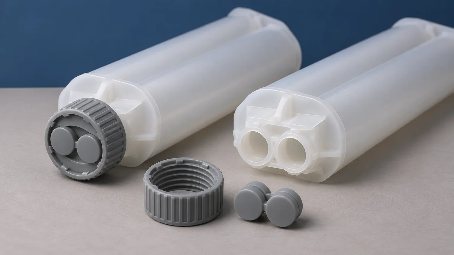
In two-component work the valve is the most visible suspect and often the wrong one. It releases a volume; the cartridge decides the ratio, the mixer decides whether the components combine, the tip decides the shape that leaves.
The cartridge and its back pressure. High restriction downstream of the mixer can push pressure back through the mix and disturb the ratio at the inlet — an off-ratio bead even when cartridge, pistons and valve are all doing their job. A bypassing piston seal reads as an unstable ratio rather than a valve fault; what to measure is in cartridge piston seals, the chain in back pressure and off-ratio beads.
The mixer. One too short for the viscosity difference, or running past its element count, delivers streaks that read as inconsistent volume. Streaks are a blend problem, short shots a volume problem, fixed by different components.
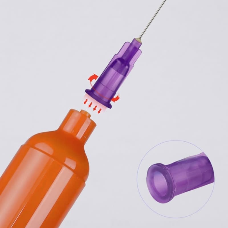
The tip and the interface. Bore, taper and hub change flow rate and where material lands; one gauge finer raises pressure drop enough to slow the shot. The effect of one gauge step is larger than most people expect, and the cheapest thing to test before a capital purchase.
A practical sequence. Measure the deposit at three points in the shift, then swap one component at a time. Changing two at once produces a number nobody can attribute.
What to send when you ask for a valve quote
Suppliers quote to the information they are given. Send these and the first reply is usually usable.
- Material and viscosity — family, filler type and loading, whether it is abrasive, and a viscosity number with its shear rate.
- Target deposit — volume or weight per shot, with the tolerance your inspection actually applies.
- Cycle time — seconds per shot, and whether that is takt or machine capability.
- Feed arrangement — cartridge, syringe, pail or bulk, the inlet interface, and whether a pneumatic gun or a pressure pot delivers it.
- Ratio for two-component work, and whether the valve sits before or after the mixer.
- Substrate and acceptance — flat, recessed, fragile or populated, and how you will prove the deposit on the first article and after.
Most quotes omit the last item, and it is the one that changes the answer: a supplier who knows you weigh deposits every two hours proposes a different valve from one told only the viscosity.
Matching a valve to a cartridge-and-mixer set?
Send the material, the ratio and the deposit you need, and we will tell you which interface and outlet the valve has to meet — or whether the defect is coming from the mixer rather than the valve.
Frequently asked questions
What are the four main types of dispensing valves?
Time-pressure, auger, piston and jet are the four metering families, distinguished by how the volume is produced. Diaphragm, needle, pinch, spool and poppet are a separate group: they switch flow on and off but do not meter it, so they are chosen alongside a metering method rather than instead of one.
Which valve type is best for high-viscosity adhesive?
Usually auger or piston. Auger ties volume to screw revolutions and handles filled pastes; piston gives the tightest repeatability where the material fills a chamber consistently. Time-pressure struggles because the viscosity term dominates the flow equation.
Why does my valve drip between shots?
Usually because nothing seals the fluid path at the tip. Time-pressure and auger designs have limited or no mechanical suck-back, so residual pressure in the column pushes material out after the command ends. A shut-off valve with suck-back, a shorter pulse, or lower reservoir pressure are the three usual fixes.
Where to go next
- Adhesive dispensing systems: the full selection guide — one level up, at the architecture the valve sits inside.
- Viscosity, pot life and cure speed — how the material variables in Table 1 are actually measured.
- Dispense tip gauge size chart — the bore decision immediately downstream of the valve.
- Common 2K dispensing defects — symptom-first diagnosis when the defect is not the valve.
Sources. Mechanism descriptions and jetting frequencies: IMAPS, Journal of Microelectronics and Electronic Packaging. Pneumatic and piezoelectric frequency ranges, positive-displacement limits: EPP Europe, “The real production is the benchmark”. Jet ratings (1,000 Hz continuous, 1,500 Hz burst, 0.5 nL): Nordson EFD PICO Pµlse. Jet ratings (up to 3,000 Hz, about 1 nL, media to 2,000,000 mPa·s): Vermes MDS 3200. Shut-off taxonomy: Dymax, “5 Types of Dispensing Valves”. Suck-back practice: Jaten Instrument technical note. All accessed 2 November 2026; manufacturer figures are published limits, not independent test results.