A filled adhesive does not fail a dispensing tip the way a clog does. It fails it slowly and quietly: the deposit drifts larger over a shift, then over a week, until an operator notices that the same program and the same pressure are laying a bead 15% wider than the qualification run. By then several thousand parts have been built outside spec.
Filled systems are where most of the value in industrial dispensing now sits — thermal interface materials, silver-filled epoxies, solder pastes, glass-filled structural adhesives. They are also the harshest thing you can put through a plastic or stainless orifice.
What the filler actually does to the tip
Three wear mechanisms, in order of how often they cause trouble:
- Bore erosion. Hard particles — alumina, boron nitride, silver flake, glass fibre — abrade the inner wall as they pass. The bore opens gradually and asymmetrically. Flow goes up, deposit weight goes up, and because the change is monotonic it looks like a process drift rather than a consumable wearing out.
- Exit burring. A worn exit edge develops a burr or a rounded lip. That changes how the fluid detaches, which shows up as stringing or a tail on the dot — a symptom people usually chase in the valve instead of the tip.
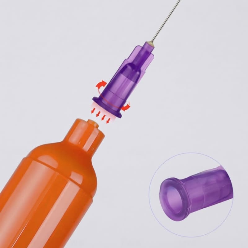
- Hub and bond failure. On a stainless cannula in a plastic hub, the bond line takes the load of every pressure pulse. With abrasive material migrating into that joint, the bond fails before the cannula wears through. The result is a leak at the base of the needle that follows the tip when you swap it.
The bore-to-particle rule, and why 3x is the floor not the target
The working rule is that the tip’s internal diameter should be at least three to five times the largest filler particle. Three times is a floor that prevents bridging; five times is where you stop seeing intermittent partial blockages.
The reason to aim higher than the floor is that bridging is a probability, not a threshold. A 4:1 bore-to-particle ratio will pass most shots and block occasionally — which is the worst possible failure pattern, because it looks like an intermittent fault and gets attributed to the valve. Convert the required internal diameter into a gauge number with the needle gauge size chart before you order.
| Filler type | Typical largest particle | Minimum ID (3x) | Recommended ID (5x) | Nearest common gauge |
|---|---|---|---|---|
| Silver flake (conductive epoxy) | 20–45 µm | 0.14 mm | 0.23 mm | 25G–27G |
| Alumina (thermal interface) | 30–75 µm | 0.23 mm | 0.38 mm | 22G–23G |
| Boron nitride (thermal) | 20–60 µm | 0.18 mm | 0.30 mm | 23G–25G |
| Glass fibre (structural) | 100–200 µm | 0.60 mm | 1.00 mm | 14G–18G |
| Silica (general purpose) | 10–30 µm | 0.09 mm | 0.15 mm | 27G–30G |
Note the direction this pushes you: filled systems usually need a larger bore than the viscosity alone would suggest. If you size by viscosity you will pick a tip that flows correctly on the first shot and bridges on the four-hundredth.
Material choices, honestly compared
| Tip material | Wear resistance | Chemical resistance | Cost | Best fit |
|---|---|---|---|---|
| 304 / 316 stainless cannula | Good | Good | Medium | Most filled systems; the default choice |
| Polypropylene (moulded) | Poor–moderate | Excellent | Low | Chemically aggressive but only lightly filled materials |
| Polyethylene (tapered) | Poor | Good | Low | Thick but soft pastes; short runs |
| PTFE-lined stainless | Good | Excellent | Higher | Fast-curing filled systems where cure-in-tip is the main risk |
| Tungsten carbide or ceramic | Very high | Good | High | Continuous high-volume abrasive work where tip changes cost more than the tip |
A caution on plastic: it is not simply “weaker”. A soft plastic bore can be gentler on some filled systems because particles embed rather than abrade, and the tip gives instead of chipping. What plastic cannot do is hold a bore dimension over a long run. If your process control depends on the deposit staying constant, the bore has to stay constant, and that means metal.
The PTFE versus stainless comparison covers the cure-in-tip side, which is a different problem from wear.
Predicting tip life instead of discovering it
You do not need a lab to get a usable number. Weigh ten deposits on a new tip, then re-weigh ten every shift and plot the mean. A drifting mean with a stable spread is bore wear. A stable mean with a widening spread is a bridging or valve problem.
When the mean has moved beyond your tolerance band, you have your replacement interval — not the interval in the supplier’s catalogue, which was measured on a different material. Then convert it to a cost per thousand shots:
cost per 1,000 shots = (tip price ÷ shots per tip) × 1,000

Example: tip at 0.45, changed every 25,000 shots
  → (0.45 ÷ 25,000) × 1,000 = 0.018 per 1,000 shots

Compare against the cost of one rejected part.
The tip is almost never the expensive part.
That calculation is worth doing explicitly, because it settles an argument that otherwise runs on instinct. A more expensive tip that lasts three times as long is usually the cheaper option once scrap and changeover labour are counted — and the labour is often the larger number.
Symptoms and what they actually mean
| Symptom | Wear-related cause | What to check first |
|---|---|---|
| Deposit weight creeps up over days | Bore erosion | Weigh 10 shots against the qualification record |
| Intermittent partial blockage, then clears | Bridging at a bore-to-particle ratio below 5:1 | Filler particle size from the TDS, versus actual ID |
| Stringing that was not there before | Burb at the exit | Inspect exit under magnification; replace tip |
| Leak at the base of the cannula | Bond failure from abrasive ingress | Whether the leak moves with the tip |
| Bead width varies side to side | Asymmetric bore wear | Whether the tip has been run at an angle to gravity |
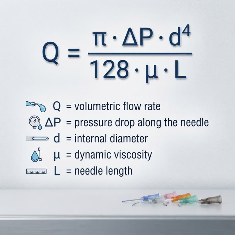
Deposit weight creeping upward is the earliest reliable signal, because bore erosion widens the effective ID and flow responds to the fourth power of diameter — the relationship itself is set out in how a change in bore changes flow rate.
The process changes that buy more life than a better tip
- Lower the pressure and widen the bore. Abrasive wear scales with velocity. Running a larger bore at lower pressure wears the tip less than a small bore at high pressure for the same flow.
- Shorten the needle. Wear happens along the length. A 12.7 mm cannula has half the wear surface of a 25.4 mm one.
- Purge before parking. Settled filler consolidates in the bore during a stop, and the first shot after restart pushes a concentrated slug of particles through the narrowest point.
- Log tip changes per line. Without a record, the replacement interval defaults to “when someone complains”, which means it is always discovered through scrap.
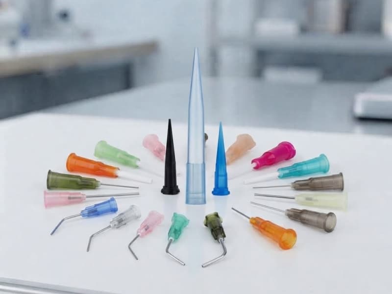
If the deposits are drifting and the tip is not the cause, the next thing to rule out is upstream mixing — incomplete mixing also changes deposit behaviour, and it is covered in common 2K dispensing defects. Bore and standoff basics are in the tip geometry guide, and the stainless, PP, PTFE and brush options are specified on the dispense tip range.
Frequently asked questions
How often should I change a dispensing tip on a filled adhesive?
There is no universal interval. Establish it on your own line by weighing ten deposits per shift and plotting the mean. The interval is the number of shots at which the mean leaves your tolerance band. Intervals reported by other plants are not transferable, because filler loading and pressure profile differ.
Can I use a plastic tip for thermal paste?
For short runs and low volume, yes. For production, the bore will not hold dimension, and thermal paste deposit weight is directly tied to thermal performance. Metal is the safer choice where the deposit has to stay inside a tolerance band.
What bore size do I need for a 50 µm filled adhesive?
At a five-to-one ratio, 0.25 mm, which is approximately 25G. Three-to-one gives 0.15 mm, but that is a bridging risk rather than a working specification. Confirm the largest particle size from the technical data sheet rather than the nominal filler loading.
Why does my tip leak at the base instead of wearing out?
Abrasive material migrates into the bond line between cannula and hub and erodes it. The joint fails before the bore does. If the leak follows the tip when you swap tips, it is a bond failure, not a valve problem.