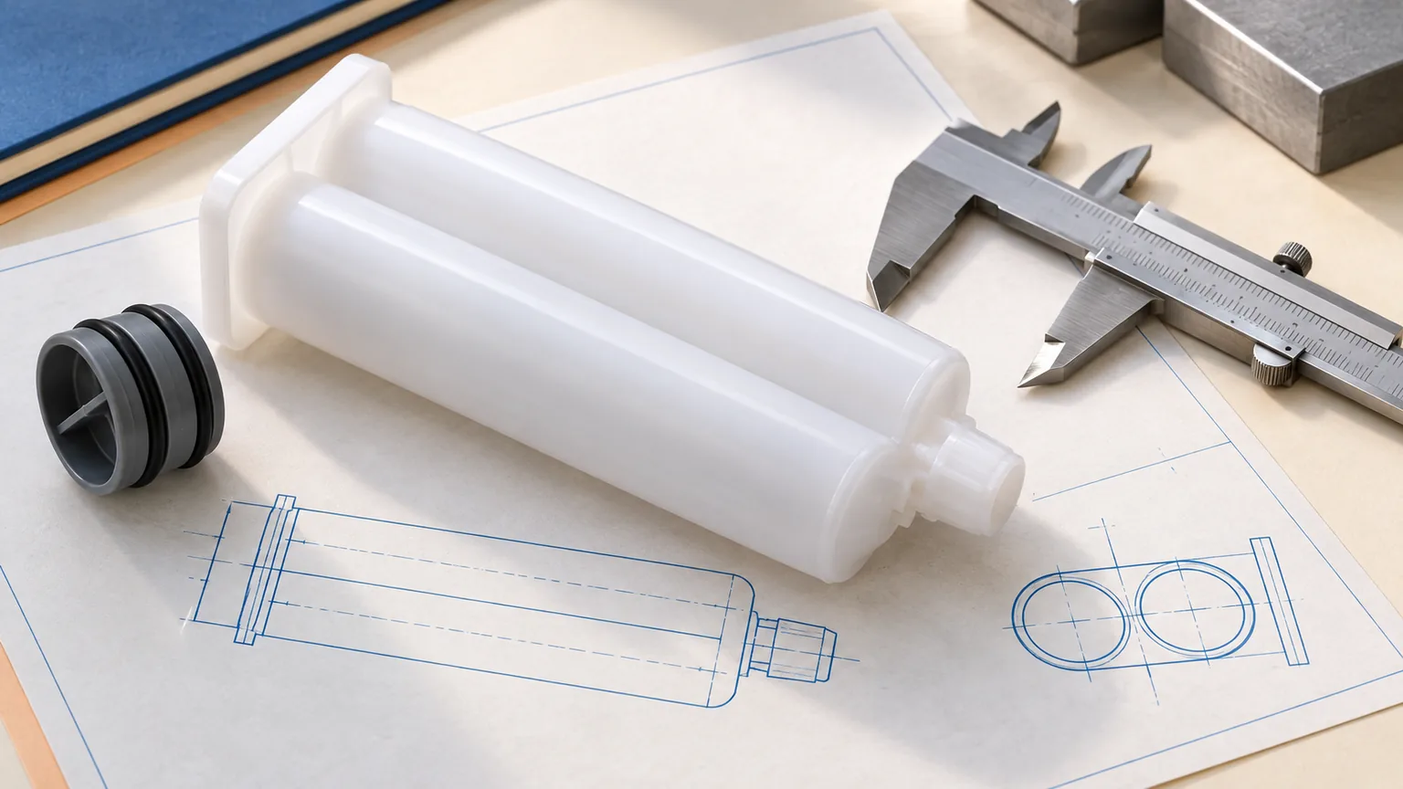
Adhesive cartridge dimensional inspection starts with an agreed drawing, not a caliper reading. Confirm the part and revision, identify the specified datums and measurement locations, then measure the barrel, outlet and piston in a defined condition using a suitable method. Record individual results against the drawing limits and an agreed acceptance rule. Two reports can disagree even when both operators use calibrated instruments if they support the plastic differently or measure different features.
This guide is for packaging engineers and supplier-quality teams accepting molded cartridges. If you are still choosing capacity or mixing ratio, start with our dual-component cartridge selection guide. Here the decision is narrower: can the delivered parts be accepted against the released requirements?
Make the drawing and the inspection report refer to the same part
A catalog sketch helps identify a cartridge. It is not automatically a production acceptance drawing. Overall length, nominal capacity and a familiar product code do not define every sealing or locating feature. Before measuring a shipment, assemble a controlled inspection package:
- Identity and revision. Match the part number, drawing revision, material variant and any approved change or deviation to the delivered lot.
- Definition of requirements. Check units, toleranced dimensions, geometric controls, applicable notes and the drawing’s stated dimensioning convention. Resolve conflicts between the drawing, 3D model and purchase specification with the design owner; do not choose whichever document gives a pass.
- Inspection locations. Give each required feature a stable report identifier. For a tapered bore, identify the axial station and direction being measured rather than reporting an undefined “inside diameter.”
- Part state and decision. State whether the part is free or restrained, how it is conditioned and supported, and what rule will be used to decide acceptance near a limit.
A supplier may use its own report numbering, provided each result maps unambiguously to your requirement. A nominal CAD dimension without an associated tolerance or other acceptance definition is a question to resolve before release, not permission to invent a tolerance. Preserve the original requirement alongside the result so a later drawing revision cannot silently change the basis of an earlier inspection.

Agree where the measurement starts and how the part is held
A datum is an ideal reference used to establish a measurement relationship. The real molded feature used to establish it is not itself perfectly flat, straight or round. KEYENCE’s datum explanation distinguishes that ideal reference from the physical datum feature and its simulator. This matters when one laboratory measures outlet height from a flange seating surface while another starts from the extreme edge of a warped flange: their numbers may describe different relationships.
Follow the datum features and precedence actually specified. A support flange, bore axis or locating face might be relevant to a particular design, but a photograph does not tell you which is datum A. If a requirement needs a reference that the drawing does not define clearly, resolve the ambiguity with engineering. An inspection fixture cannot quietly substitute its own datum scheme.
Thin molded walls also make the holding condition part of the measurement. Separate these cases:
- Free-state requirement. Use support that does not force the part into a preferred shape. Document where it rests and how repeatably it can be located.
- Specified restrained condition. Reproduce the approved fixture contacts and restraint. Record the fixture identity and loading method rather than clamping until the reading looks acceptable.
Neither state is universally correct. A flange can appear flatter under a clamp, while the same restraint changes the adjacent barrel shape. That does not prove the part has improved; it means the measurement condition changed. Keep free-part dimensions, restrained dimensions and assembled-fit observations as distinct results when the specification calls for them.
Inspect functional features, not just overall length
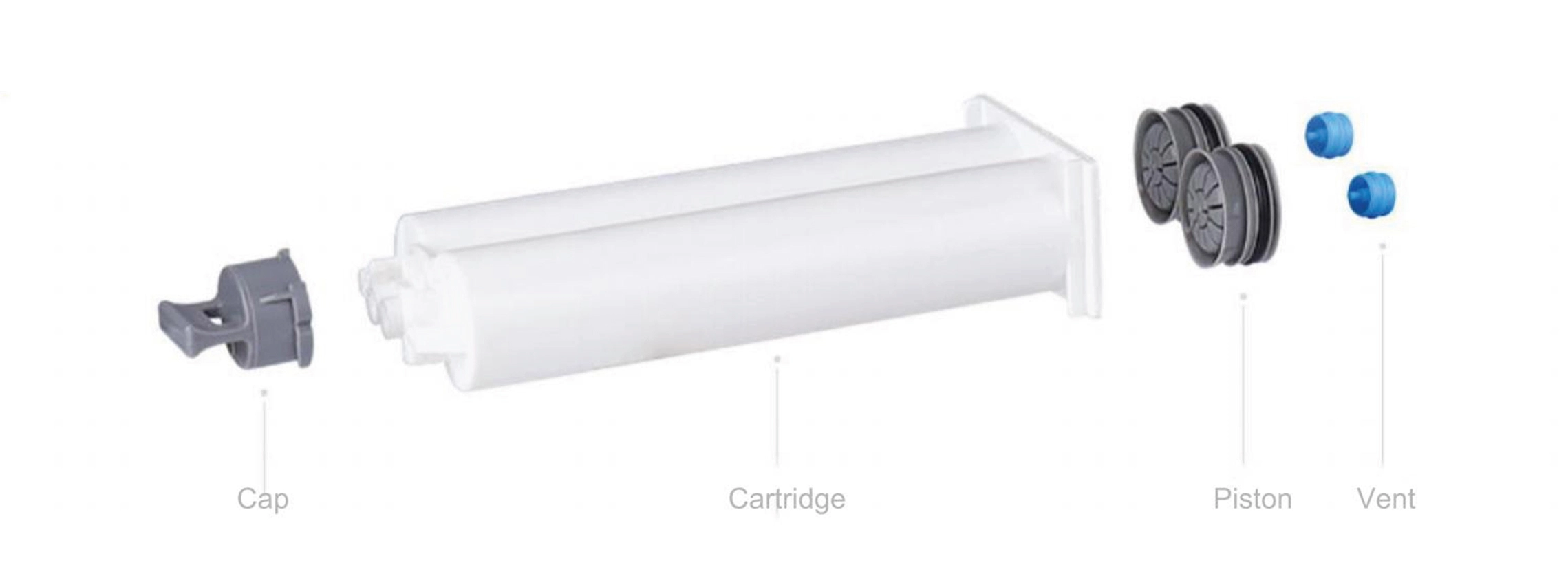
For a dual cartridge, inspect both chambers where the drawing requires it. Equal-looking barrels do not establish equal bore geometry, and a nominal capacity label is not a dimensional report. Build the inspection sequence around the actual sealing, guiding and locating features.
Cartridge feature-to-method inspection matrix
Planning guide, not universal tolerances. On a narrow screen, swipe to see every column.
| Feature | Define before measuring | Method to evaluate | Avoid this false conclusion |
|---|---|---|---|
| Barrel bore | Chamber identity, axial stations, directions and the specified size or form requirement. | Suitable internal measurement or validated optical/coordinate method; control contact force and access. | A diameter reading at the open mouth proves the entire piston travel is conforming. |
| Barrel wall | Local wall locations, access and whether the requirement concerns thickness or geometry. | Accessible low-force thickness measurement; a qualified alternative for hidden sections. | Subtracting one ID from one OD proves the minimum wall everywhere. |
| Outlet and closure seat | Seal face, locating features, opening and any defined thread or locking geometry. | Optical or coordinate inspection; specified functional gauges for the particular interface. | A closure or mixer that can be attached proves every interface dimension passes. |
| Flange and locating faces | Reference features, seating condition and any specified flatness, orientation or location controls. | Approved support/fixture with an appropriate height, form or coordinate method. | A caliper reading at one edge proves face flatness or outlet alignment. |
| Piston and seal features | Separate part identity, profile/location and free or assembled condition. | Validated low-force or optical method that does not flatten the feature being checked. | A compressed seal diameter represents its unloaded profile or predicts sealing performance. |
Bore size needs a location. Molded geometry may include intended draft. Readings at different depths can therefore differ without describing the same requirement. If your inspection plan calls for multiple stations and directions, retain them separately. Do not average a large and a small result into a passing mean unless the requirement explicitly defines that measurand. A small set of two-point readings also does not establish cylindricity; a form requirement needs a method capable of assessing that form.
Wall thickness needs a local definition. The expression (OD − ID) / 2 describes a uniform concentric circular section. It does not establish the thinnest wall of an eccentric or nonuniform molded part, and diameters from different axial planes cannot simply be combined. Where minimum local wall matters, define how that wall is accessed or assessed. If sectioning is approved, identify the cut plane and preparation method because the sample is altered.
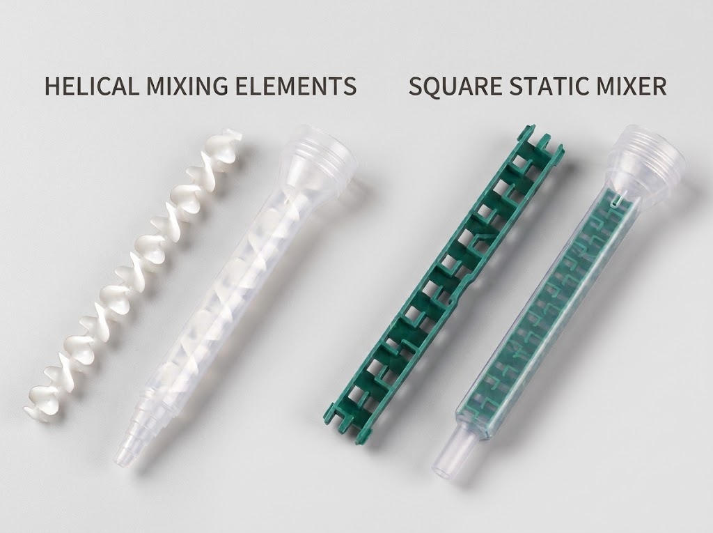
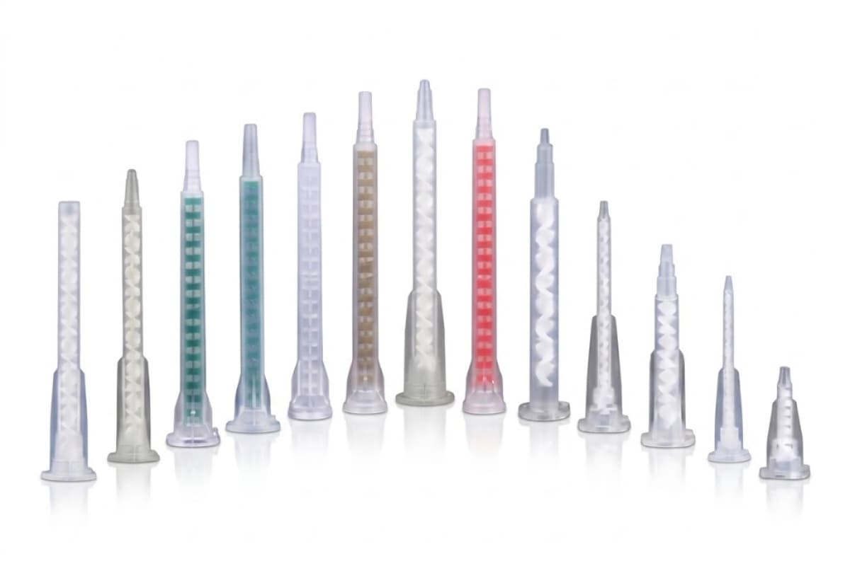
The interface contains more than an opening. A closure may engage while its sealing face seats incorrectly. Check the dimensions or controls actually defining the interface and use the approved mating component revision for a separate fit check. Keep the scope at the cartridge: selecting retainers or adapters is a different engineering task.
Select a measurement method that does not change the feature
On a flexible plastic barrel, closing ordinary caliper jaws more firmly can change the measured section. Mitutoyo’s plastics metrology guidance describes the risk of deforming plastics with tactile measurement and the role of low-force or non-contact methods. The practical choice is not “contact bad, optical good.” It is whether the proposed method measures the defined feature without an uncontrolled influence.
A contact instrument can be suitable for an accessible feature if its contact geometry, force and support are appropriate. Check that reseating the part and repeating the measurement do not introduce variation that makes the acceptance decision unreliable. A calibration sticker alone does not evaluate that setup.
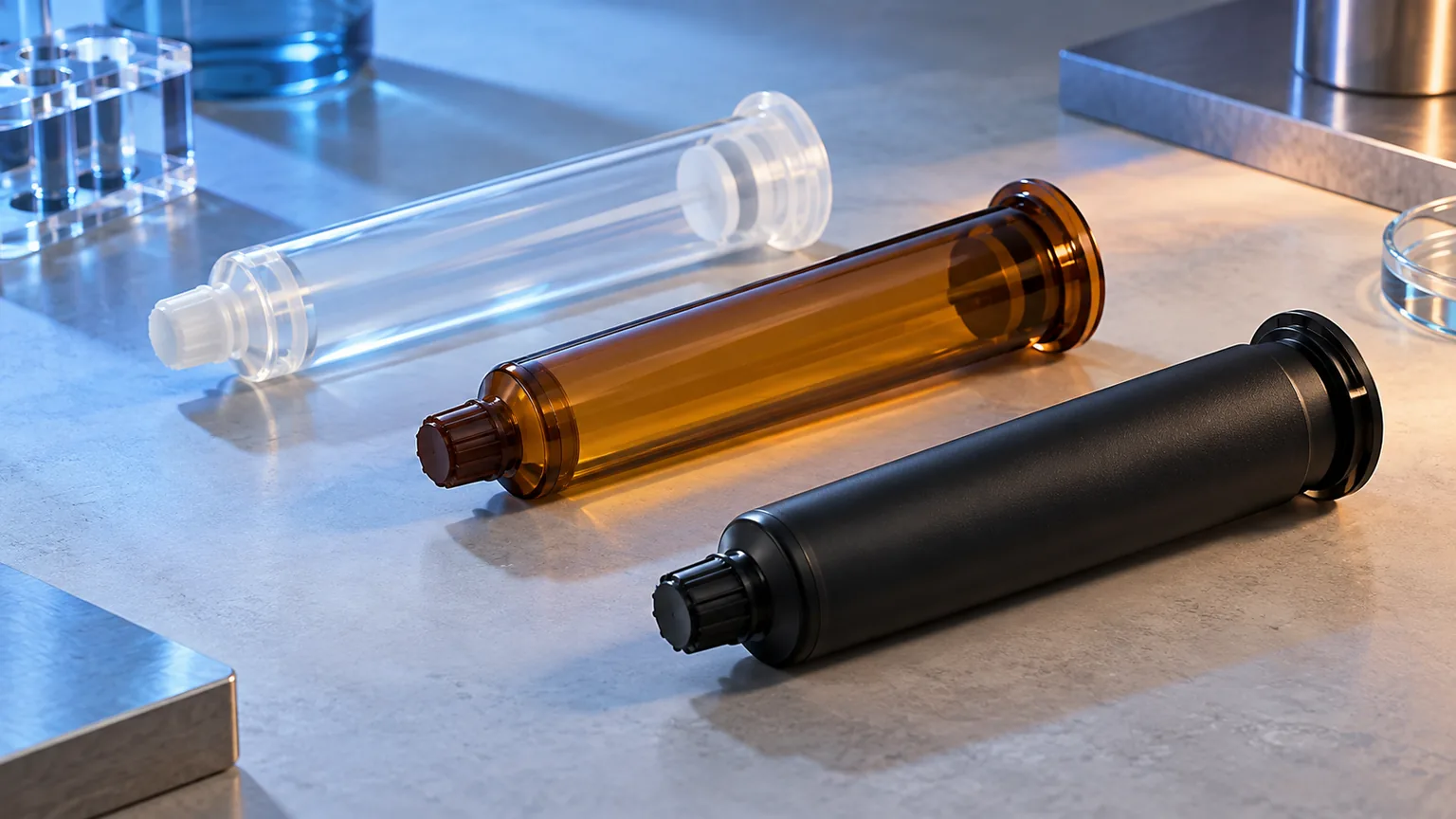
Optical methods avoid probe compression, but edge definition still matters. Transparent or translucent walls can produce competing boundaries; lighting, focus and edge-selection settings can change which boundary is reported. Validate the program against the intended feature and preserve those settings. For a hidden feature, agree a qualified method with the supplier or a capable metrology provider rather than assuming an external measurement represents the inaccessible interior.
Digital resolution is not the same as measurement uncertainty. NIST’s metrological traceability guidance, especially FAQ 5.1.4, explains that traceability alone does not establish fitness for purpose. For this inspection, judge the method against the tolerance and decision risk, considering influences such as fixturing, force, alignment, edge detection, repeatability and the part’s condition. There is no single instrument-to-tolerance ratio that this guide can safely prescribe for every cartridge.
Keep conditioning and sample identity with the readings
A molded part measured soon after production and one measured after storage may not represent the same condition. Temperature, time after molding and, for moisture-sensitive materials, moisture conditioning can affect the comparison. Follow the drawing or agreed material-specific procedure. Do not impose an arbitrary conditioning time or copy a temperature from an unrelated test.
Before comparing reports, record the material variant, relevant conditioning history, measurement environment and time. If the supplier and receiver use different conditions, establish whether that difference is significant for the feature before attributing the disagreement to the mold.
Sampling is a separate agreement, not a number to improvise in a dimensional article. Identify the lot and available cavity markings, and retain a link from each inspected part to its results. Where the approved plan requires coverage of multiple cavities or production periods, do not replace it with a handful of convenient samples from one box. Conversely, do not claim that a dimensional sample proves every unmeasured part meets every requirement.
When two reports disagree, compare the method on the same parts
Immediately changing the drawing to match one laboratory’s result can hide the cause. Use retained, identified samples to distinguish a measurement-system difference from a real part difference:
- Match the definition. Confirm revision, units, feature identifier, station, direction, datum alignment and free or restrained condition. A mismatch here means the readings are not yet comparable.
- Check the setup. Verify instrument status, reference checks, fixture seating and the applicable program. Examine contamination, flash or damage without altering the sample and then calling it an untouched incoming part.
- Repeat with reseating. Measure the same identified parts using the agreed method, removing and repositioning them between repetitions. Where relevant, involve another operator. Preserve individual readings and the order rather than retaining only a favorable average.
- Review the remaining difference. Compare the spread and the methods’ evaluated uncertainties with the acceptance question. Use a better-qualified method or an agreed independent measurement if the current setup cannot resolve the decision.
If the results change substantially with clamping or probe force, that is evidence to investigate the method, not permission to select the lowest reading. If a cavity-related difference remains under the common method, isolate the affected material while engineering evaluates it. Repeating an unsuitable measurement more times does not make its result suitable.
Define what happens near a tolerance limit
The acceptance rule should be agreed before inspectors see a borderline result. Some programs use direct comparison with the tolerance limits; others require a margin that accounts for uncertainty. Those choices allocate decision risk differently. State the actual rule in the inspection agreement and report, rather than silently switching rules when a shipment is urgent.
Illustrative example: a nominally in-limit result still needs review
Assume an invented length requirement of 20.00 ± 0.10 mm, giving limits of 19.90 to 20.10 mm. Also assume the parties agree to direct acceptance only when the reported expanded-uncertainty interval lies wholly within those limits.
- A result of 20.08 mm with U = 0.03 mm gives the reported interval 20.05–20.11 mm. The reading is inside the tolerance, but the interval crosses its upper limit. Under this example rule, hold the decision for review rather than mark it accepted.
- A result of 20.04 mm with the same U gives 20.01–20.07 mm. That interval is contained within the limits, so it meets this particular direct-acceptance condition.
These are hypothetical values, not Haijing tolerances or test results. U represents an evaluated expanded uncertainty with stated coverage conditions, not the instrument’s display increment; its interval is not an absolute guarantee of the true value. A different agreed decision rule can produce a different disposition.
Do not label an unresolved borderline result a proven defect merely because direct acceptance was not demonstrated. Record the result and the rule, then follow the agreed escalation path. Engineering may require a more capable measurement, an explicit deviation decision or another defined action. Inspectors should not round away an unfavorable digit or silently widen the requirement.
Separate dimensional acceptance from assembly performance
A cap that fits and a piston that moves provide useful functional observations, but they do not erase an out-of-specification feature. Likewise, passing drawing dimensions alone does not establish leak resistance, pressure capability, chemical compatibility or formulation stability. Keep dimensional results and any separately approved functional tests in distinct records.
For a discrepancy, identify and contain the affected lot, preserve representative parts and record the exact requirement and observation. First resolve definition or method errors. If nonconformity is confirmed, the authorized engineering and quality owners must decide the disposition: rejection, approved rework, replacement or a documented concession where permitted. Reinspect against the authorized disposition and retain the original result. Do not relabel unapproved reworked parts as conforming untouched parts.
Before release, the report should connect these essentials:
- Requirement: part/drawing revision, feature identifier, limit and applicable notes.
- Evidence: sample/lot identity, datum and restraint condition, measurement method, relevant settings and individual results.
- Decision: applicable uncertainty information and acceptance rule, exceptions, authorized disposition and release approval.
Haijing’s custom development process includes DFM feedback and an FAI report for customer sign-off. The broader cartridge and mixer OEM/ODM guide explains where that approval sits in development. For a specific cartridge, agree which features and measurement conditions the report must cover; the availability of an FAI service does not itself define your tolerances or prove a particular metrology capability.
Questions about cartridge inspection reports
Can an approved physical sample replace the drawing?
A retained sample can support comparison, but it does not define every limit or geometric relationship. If it is part of acceptance, identify it, control its condition and state exactly what is compared. Do not infer a numerical tolerance from one sample or use it to override a conflicting released drawing without authorization.
Do we need a full dimensional report for every incoming shipment?
That depends on the approved inspection plan, feature risk, supplier performance and any changes. Initial qualification and routine incoming inspection may have different scopes. Record the agreed scope and any trigger for expanded checks; a prior report from another lot is not a measurement of today’s shipment.
Can a 3D scan automatically settle a dimensional dispute?
No. The scan still needs a suitable acquisition method, datum alignment, feature extraction and uncertainty evaluation. A color deviation map from a general best-fit alignment may answer a different question from a drawing-controlled feature. Compare the specified requirement, not only the appearance of the map.
Technical references
- KEYENCE: What Are Datums? — conceptual reference versus real datum feature; follow the governing convention on your drawing.
- Mitutoyo: Plastics Metrology Solutions — deformation risk and low-force/non-contact approaches.
- NIST: Metrological Traceability FAQ — traceability, uncertainty and fitness for purpose, particularly sections 5.1.4 and 5.1.7.