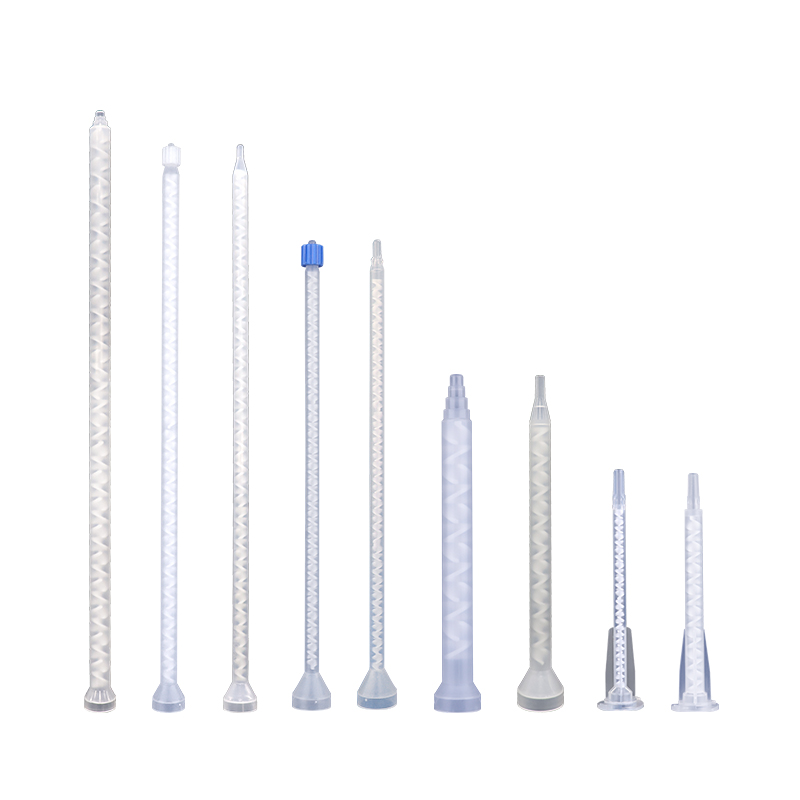
Static Mixing Nozzles: The Complete Engineering Guide for Two-Component Adhesives
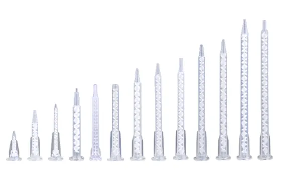
How Static Mixers Work Without Moving Parts
       [Cartridge Outlet]
               │ (Resin A + Hardener B enter under pressure)
               ▼
┌──────────────────────────────┐
│  Stage 1: Fluid Division     │ ➔ Element splits streams into 2 sub-layers
└──────────────┬───────────────┘
               ▼
┌──────────────────────────────┐
│  Stage 2: Radial Rotation    │ ➔ 180° twist rotates layers outward
└──────────────┬───────────────┘
               ▼
┌──────────────────────────────┐
│  Stage 3: Recombination      │ ➔ Interlocking elements force sub-layers
└──────────────┬───────────────┘    to re-merge exponentially (2^N)
               ▼
      [Homogeneous Dispense]
-
Division: The leading edge of each internal element splits the oncoming adhesive stream into two distinct sub-layers.
-
Rotation: The helical or geometric structure rotates the fluid 180 degrees (alternately clockwise and counter-clockwise), pushing interior layers toward the outer pipe wall and vice versa.
-
Recombination: The trailing edge meets the perpendicular leading edge of the next element, forcing the divided sub-layers to interlock and re-merge.
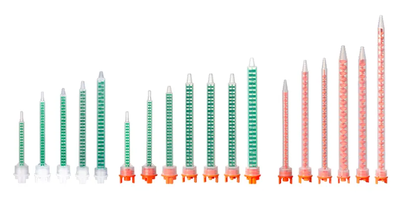
Anatomic Breakdown: Internal Element Geometries and Housing
| Feature / Metric | Helical (Spiral) Elements | Square (Quad / Turbo) Elements |
| Primary Geometry | Alternating 180° left- and right-hand helical twists. | Compact, interleaved square geometric baffles. |
| Fluid Shear Efficiency | Standard; requires longer housing length for complete mixing. | High; achieves equivalent homogeneity in ~50% shorter length. |
| Pressure Drop | Lower resistance; optimal for manual dispensing guns. | Higher localized resistance; requires stable pneumatic pressure. |
| Retained Material Waste | Higher volume retained due to total housing length. | Significantly reduced waste volume upon disposal. |
| Viscosity Suitability | Excellent for medium-to-low viscosity fluids and equal ratios. | Ideal for high-viscosity, wide-ratio (10:1) formulations. |
Materials and Housing Integrity
Interface Classification: Understanding A, B, C, and F Systems
                  ┌───────────────────────────────┐
                  │    Cartridge Interface System │
                  └───────────────┬───────────────┘
                                  │
      ┌────────────────┬──────────┴───────────┬────────────────┐
      ▼                ▼                     ▼                ▼
[ System A ]     [ System B ]          [ System C ]     [ System F ]
  (Bayonet)      (Snap-Lock)           (Threaded)       (Twist-Lock)
  Small 2K        Low-Visc.            High-Volume      High-Pressure
 50/75ml        50/75ml            200-400ml        200-400ml
System A (Bayonet Interface)
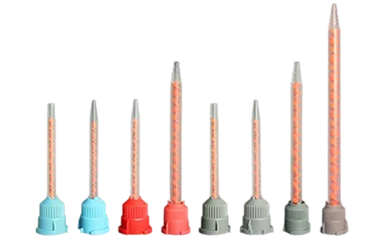
System A features a twist-and-lock bayonet lug mechanism. It is compatible with 1:1, 2:1, 4:1, and 10:1 ratio cartridges and is commonly specified for smaller 50ml dual cartridges. The twist-lock design aligns internal ports directly with cartridge outlets, preventing cross-contamination at the interface prior to dispensing. While it works across all standard ratios, for 4:1 and 10:1 applications, System B is the preferred choice due to its superior alignment rigidity under differential backpressure. Explore System A bayonet static mixers for small-scale manual applications.
System B (Snap-Lock / Slide-Lock Interface)
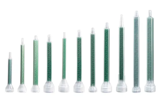
Designed for small-volume dispensing, System B employs a push-and-lock sliding shroud. It is compatible with 1:1, 2:1, 4:1, and 10:1 ratio cartridges. The sliding shroud provides greater alignment rigidity, which is especially critical for non-equal mixing ratios (4:1 and 10:1) where differential backpressure between Part A and Part B can cause cross-port leakage. For these two ratios, System B delivers noticeably better performance than System A. Review System B static nozzles for mid-capacity configurations.
System C (Heavy-Duty Threaded Interface)
System C incorporates a separate threaded retaining nut over a flanged nozzle inlet. This interface accommodates high backpressure without axial slippage, making it the standard for 200ml to 400ml industrial cartridges dispensing high-viscosity structural epoxies. System C is fully suitable for manual dispensing operations. Browse System C high-capacity static mixers for high-viscosity applications.
System F (High-Pressure Twist-Lock Interface)
System F features an integrated flange and keyway structure designed for dedicated application systems. It maintains tight port separation to eliminate inter-port curing (plugging) during cartridge storage and reuse cycles. System F works well for both manual and pneumatic/automated setups; however, in pneumatic or high-pressure automated systems, it outperforms System C due to its more secure port sealing and resistance to pressure-induced leakage. Check System F twist-lock static mixers for high-pressure automated or pneumatic operations.
Engineering Selection Framework: Calculating Element Count, Diameter, and Ratio
                   ┌───────────────────────────────┐
                   │    Adhesive Mix Parameters    │
                   └───────────────┬───────────────┘a
                                   │
         ┌─────────────────────────┴────────────────────────┐
         ▼                                                  ▼
[ Viscosity Match ]                                 [ Ratio Variance ]
  • <5,000 cPs   ➔ 12-24 Elements                     • 1:1 / 2:1   ➔ Standard Count
  • >50,000 cPs  ➔ 32-48 Elements                     • 4:1 / 10:1  ➔ +25-50% Elements
Step 1: Evaluate Volumetric Ratio
Step 2: Account for Resin Viscosity
Step 3: Determine Element Count Guidelines
- 1:1 / 2:1 Epoxies & Polyurethanes: Typically require 12 to 24 elements (Helical) or 12 to 20 elements (Square).
- 4:1 / 10:1 Structural Acrylics: Typically require 24 to 32 elements (Helical) or 20 to 24 elements (Square).
- Wide Viscosity Differentials (e.g., Liquid Resin + Paste Hardener): Require up to 48 elements or integration of dynamic element heads depending on fluid flow dynamics.
Note: Exact element requirements depend on resin chemistry, manufacturer guidelines, and operating temperature.
Static vs. Dynamic Mixers: When to Upgrade
| Parameter | Static Mixing Nozzle | Dynamic Mixing Nozzle |
| Operating Mechanism | Passive fluid split via stationary geometry. | Motorized internal element actively shearing fluid. |
| Viscosity Limits | Ideal up to ~100,000 cPs. | Handles extreme thick pastes (greater than 500,000 cPs). |
| Mix Ratio Capability | Performs reliably up to 10:1 ratio. | Handles wide, extreme ratios (>20:1). |
| Viscosity Differential | Requires compatible component flow rates. | Mixes water-thin hardeners into heavy pastes easily. |
| Maintenance / Cost | Disposable; low unit cost; zero maintenance. | Reusable assembly requiring solvent wash/purging. |
Troubleshooting Common Dispensing & Curing Issues
                    ┌───────────────────────────────┐
                    │  Dispensing Issue Identified  │
                    └───────────────┬───────────────┘
                                    │
      ┌─────────────────────────────┼───────────────┐
      ▼                             ▼                             ▼
[ Soft/Uncured Joint ]      [ Housing Swelling/Burst ]    [ Bubble Entrapment ]
  • Insufficient elements     • High fluid backpressure     • Air pockets in nozzle
  • Interface cross-leak      • Undersized nozzle ID        • High dispense speed
1. Incomplete or Soft Curing
- Root Cause A: Inadequate element count, leaving unmixed resin striations.
- Root Cause B: Cross-port contamination at the cartridge neck causing pre-cure blockage.
- Solution: Increase element count by 4 to 6 units or verify that the interface system matches the cartridge style (e.g., switching from System A to System F).
2. Nozzle Housing Swelling or Splitting
- Root Cause: Excessive fluid backpressure caused by dispensing high-viscosity material through a narrow internal diameter or using an excessive element count with manual applicators.
- Solution: Select a larger nozzle inner diameter (e.g., from 5.3mm to 6.3mm or 8.0mm) or switch to a high-efficiency Square geometry to reduce nozzle length.
3. Air Bubble Entrapment in Dispensed Bead
- Root Cause: Air pockets trapped inside the empty mixer during initial purge, or excessive dispense speed causing fluid cavitation.
- Solution: Hold the dispensing gun vertically (nozzle pointing upward) during initial priming until all air is purged before applying material to the substrate.
Procurement & Quality Verification Checklist
- [ ] Chemical Compatibility: Confirm whether polypropylene housing and acetal elements are chemically resistant to your specific resin, solvent, or catalyst formulation.
- [ ] Cartridge Alignment: Verify that the mixer connection system matches your existing cartridge inventory (System A, B, C, or F).
- [ ] Pressure Ratings: Ensure the nozzle burst pressure rating exceeds the pneumatic output capability of your automatic dispensing equipment.
- [ ] Dimensional Tolerances: Confirm nozzle tip diameters match automated dispensing tip attachments (Luer Lock vs. Stepped Tip) if fine-bead application is required.
- [ ] Batch Consistency: Validate supplier manufacturing controls to ensure consistent element molding and prevent inner diameter variations.
Summary & Next Steps
Need assistance selecting static mixing nozzles for two-part epoxy or automated dispensing lines? Request Custom Static Mixer Samples or submit your fluid viscosity and cartridge specifications to HaiJing’s technical engineering team for custom selection support.
Key Takeaways
- Static mixers rely on passive fluid division, rotation, and recombination, generating 2 to the power of N fluid striations across N elements without moving parts.
- Square (Turbo) elements reduce mixer length and material waste by roughly 50% compared to traditional Helical elements while providing high mixing shear.
- Cartridge interfaces (System A, B, C, and F) must match the cartridge neck precisely to prevent cross-contamination and withstand dispensing pressure.
- Higher mix ratios (4:1, 10:1) and viscosity differences require additional elements (20%–40% increase) to achieve thorough chemical activation.
- Matching nozzle inner diameter to fluid viscosity prevents backpressure buildup, housing expansion, and seal failure during dispensing.
FAQ
Can disposable static mixers be cleaned and reused?
What happens if a static mixer has too few or too many elements?
How do I match my cartridge size (50ml, 200ml, 400ml) to the right system mixer?
Contact Haijing engineers for more support
Need precise fluid mixing for non-standard adhesive ratios or high-viscosity resins? Contact HaiJing’s engineering team today to Request Custom Static Mixer Samples or receive an optimized dispensing system recommendation tailored to your production parameters.
For epoxy-specific procurement, sample approval, and retained-material checks, use our epoxy mixing nozzle buying guide before releasing a bulk nozzle specification.
When a drawing or label includes an unfamiliar identifier, use the static mixer part-number guide to separate supplier code fields from the evidence needed for replacement approval.