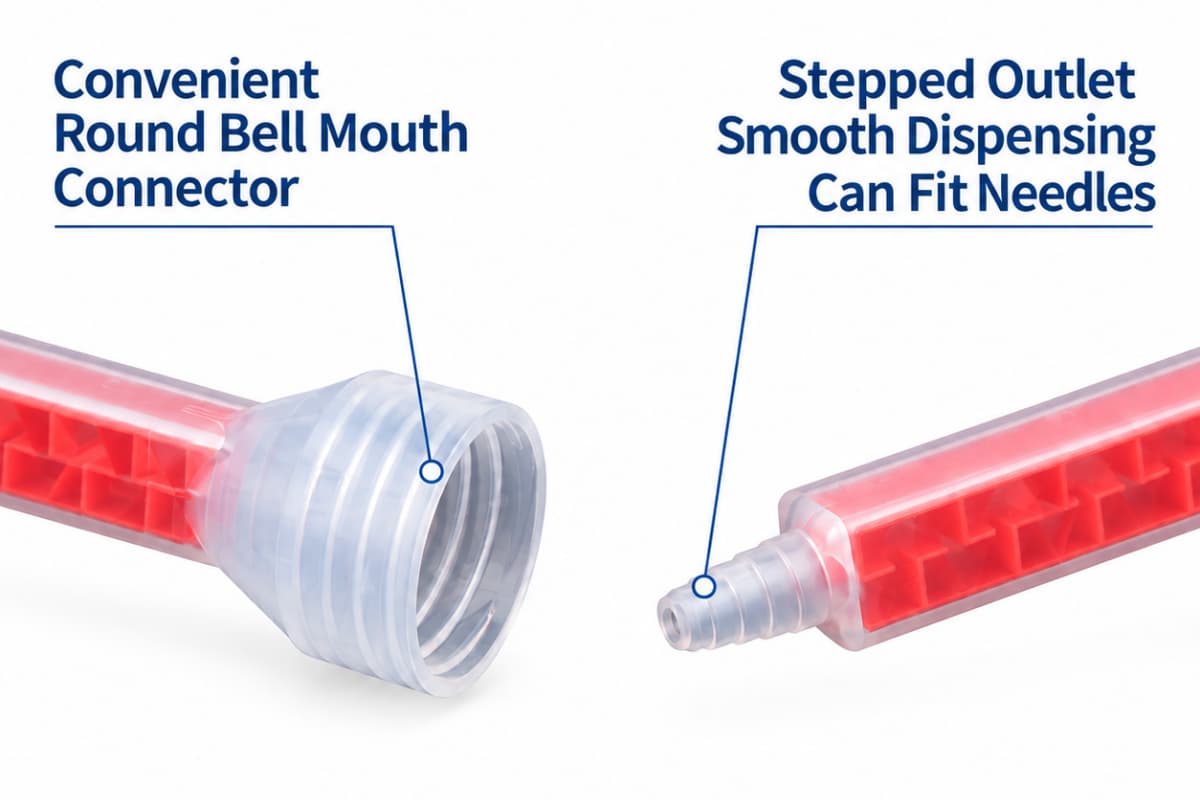
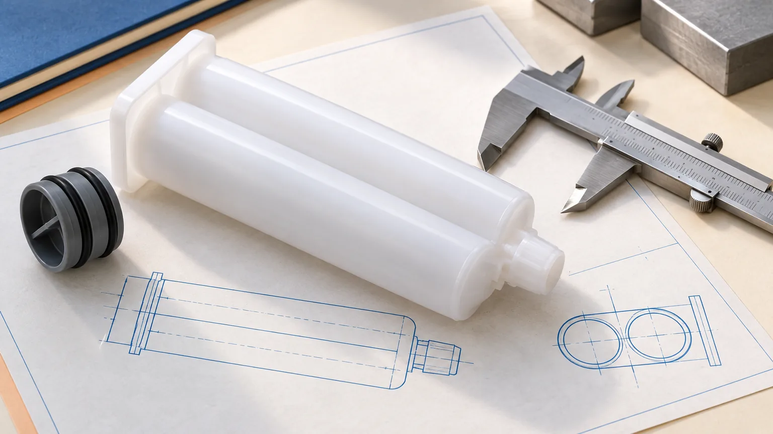
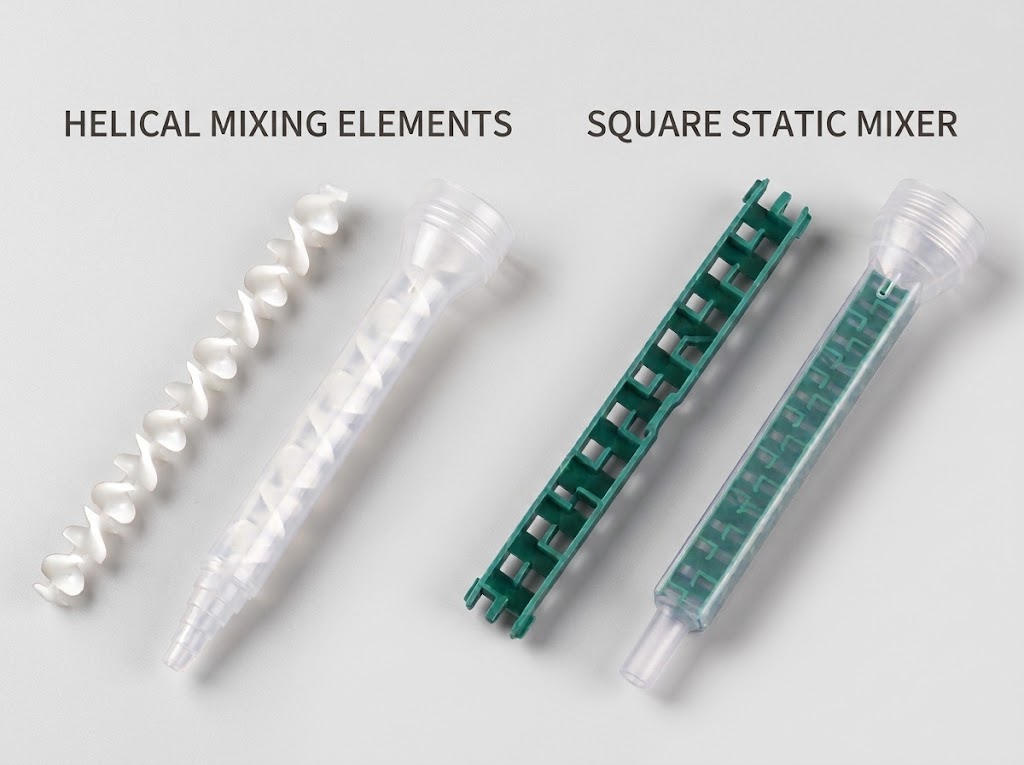
A 3D-printed static mixer is useful when you need to see whether a proposed flow path can be built, connected and screened before committing to a mold. It is not, by itself, proof that an injection-molded disposable mixer will give the same pressure loss, mixing result or service life. The right question is which decision the printed part is allowed to settle—and which decisions need a production-representative part and a new test.
What does a printed mixer actually prove?
“Prototype validated” is too broad to guide a tooling purchase. Separate three levels of evidence. A form-and-fit prototype checks envelope, cartridge connection, assembly access and whether a proposed insert can occupy the available space. A functional screening prototype can compare candidate paths under stated conditions: for example, whether a redesigned element allows the target flow while producing a usable mixed output. A production release requires the final material, manufacturing method, interface, process controls and acceptance tests. Passing one level does not imply the next.
Published work demonstrates why printing has value. Researchers have fabricated and evaluated several printed mixer geometries while measuring pressure drop in a continuous-flow experiment; newer open-access work also uses additive manufacturing to fabricate computationally designed mixer shapes. Those are evidence that printing can accelerate design exploration, not transferable performance data for a two-component epoxy cartridge. Their fluids, dimensions, construction and test rigs differ from a disposable nozzle on a customer’s line.1, 2
For a cartridge mixer, keep the first prototype question small. If you are checking only latch clearance and outlet location, a dry fit may be enough. If you want to compare mixing elements, the trial must use the real A/B material or a justified surrogate, a defined flow, the correct cartridge and an appropriate mix-quality method. If you want a production claim, the printed part alone is the wrong final specimen. Our general mixer selection guide covers element-count and diameter levers; this article covers what a manufacturing-route change does to the evidence behind that selection.
Printing, machining and molding answer different questions
The three routes are not a simple ladder from “rough” to “precise.” A printed one-piece internal path may be feasible where a cutting tool cannot reach; a machined split assembly may make a passage easy to inspect but add a joint; a molded insert and housing may be the intended disposable architecture but require tool design and process development. Compare the route against the same required geometry and test objective. Do not substitute a generic price or tolerance ranking for the supplier’s drawing, process and measured part.
Route selection for a disposable cartridge-mixer project
On a narrow screen, swipe this table to see all columns.
| Route | Best first question | What to inspect | What cannot transfer automatically |
|---|---|---|---|
| Polymer 3D print | Can this inlet, insert and outlet concept be assembled and screened quickly? | As-built channel opening, layer or support marks, trapped material, joint/seal, material identification and print orientation. | Final molded resin response, molded surface, tool-to-tool dimensions, lot repeatability and production economics. |
| Machined prototype or split insert | Can accessible faces and critical dimensions be checked before molding? | Tool access, burrs, surface finish, alignment and sealing of any split assembly. | Behavior of a later one-piece or molded assembly; an added seam may change leakage and flow. |
| Pilot or production mold | Can the intended material and part architecture meet agreed requirements repeatedly? | First-article dimensions, molded channel and element condition, assembly, process window and lot traceability. | A successful first shot does not release every cavity, lot, adhesive or dispense setting. |
A printed final part is possible when its exact process, material and repeatability are qualified for the application. This guide does not declare printing categorically unfit for production. For a disposable two-part adhesive mixer, however, changing from print to injection mold changes enough variables that a print-only test cannot release the molded version. The production drawing, polymer, tool and test plan must be approved on their own merits.
Start with the flow path, not the printer setting
Before making a part, fix the identity of the comparison. Define the cartridge outlet and retention feature, A/B inlet separation, mixer bore or open area, element profile and count, outlet type, and allowable overall length. Record whether the concept is a one-piece printed mixer, a printed insert in an existing housing, or a printed housing around an existing insert. Those are different assemblies. A changed outer shell might leave the internal path unchanged; a changed element pitch might alter both pressure loss and mixing. Keep drawing revisions distinct rather than treating similar-looking nozzles as the same sample.
The fluid decision matters just as much. Use the adhesive manufacturer’s mix-ratio basis and handling instructions; note each component’s viscosity with its test temperature and method, target flow, working life, planned stop interval and cure or mixed-output acceptance method. A 1:1 label alone does not tell you whether a geometry can handle a high viscosity mismatch. If those inputs are not yet available, the print can still answer a dry-fit question, but it cannot support a meaningful mix-quality claim.

Call out the features that are difficult to inspect after fabrication. NIST’s additive-manufacturing test-artifact guidance treats measured geometric accuracy and surface roughness as part of characterizing an as-built print, rather than assuming the model describes the delivered part.3 In a resin-printed enclosed passage, unremoved resin can obstruct the path; one primary microfluidic study also reports leakage and fracture during channel cleaning in its particular design. The study is not a mixer limit, but it identifies a practical inspection question: can the entire channel be cleared and verified without damaging the part?4
Inspect the as-built prototype before running adhesive
A successful print file only says a build was attempted. Put the prototype through a short incoming check before it reaches a dispenser. If an enclosed passage cannot be inspected or cleaned with the chosen process, redesign for access or select another prototype route. Do not push reactive adhesive through a suspected blocked channel to “see if it clears.”
- Identify the build. Save the CAD revision, process, actual material, machine/build identifiers, orientation, post-cure or finishing route, and any repair or rework. Without that record, a favorable test cannot be reproduced.
- Check the interface. Measure the mating dimensions and confirm that the retaining feature seats on the intended cartridge without forcing it. Dry-check alignment and leakage paths. A visual fit is not a pressure rating.
- Verify the passage. Inspect the inlet separation, element edges, bore, outlet and any seam or trapped support/uncured material. Use a method that can actually see the critical area: sectional sample, borescope, suitable imaging or a documented flow check, chosen for the geometry.
- Inspect after cleaning. Record the cleaning method and recheck for blocked sections, loose debris, damage or leakage. Cleaning success for one print does not prove all prints or all materials.
- Decide what remains unproven. If the trial is only for form and fit, label it so. Do not translate “assembled correctly” into “safe at production pressure.”
Material compatibility is another open item, not a visual property. A printed photopolymer, filament and injection-molded PP, PA or PBT are not interchangeable solely because they have similar shapes. Obtain the exact material data and the adhesive maker’s compatibility requirements; test exposure, working time and cleaning if they matter to the application. Do not infer chemical resistance from the generic words “resin,” “nylon,” or “engineering plastic.”
Run a fair functional screen, then label its limits
If the prototype passes inspection, compare it with a current approved mixer or a second candidate under a defined experiment. Hold the adhesive batch, A/B ratio, cartridge, outlet, material temperature, dispenser, flow target and pause schedule constant where the design allows. When an interface must change, label the result a whole-assembly comparison; a pressure or bead difference cannot then be assigned to the internal element alone.
Measure the deposited quantity over a timed interval at the required cycle rate. Record inlet and outlet pressures if the fixture has properly located sensors; only their difference at the same flow supports a claim about mixer pressure drop. Without those taps, record the dispenser setting or effort and actual output as a system-level observation. Evaluate mixed output using the adhesive maker’s applicable cure, color-distribution, hardness, bond or other method—whichever actually detects incomplete mixing for that formulation. Appearance alone may miss a ratio or cure defect. Mixer pressure loss, mixing quality, retained waste and residence behavior are distinct characteristics, as medmix’s technical treatment explains.5
Include start-up and a restart after the longest realistic pause. Reactive material can dwell in the mixer while the line is stopped, so a continuous-flow-only demonstration may answer the wrong production question. If the printing material or assembly has no documented safe operating limit for the planned dispenser, do not run a high-pressure trial; use a rated fixture and seek a production-representative sample instead. The applicable pressure and safety limits must come from the actual cartridge, mixer, dispenser and adhesive documentation, not from this article.
Nordson EFD’s selection guidance ties element choice and diameter to fluid properties, backpressure and required flow. That is a reason to test under the buyer’s conditions, not a universal element-count rule.6 For the full epoxy flow-window method, see our controlled flow-test guide; the question here is how much of that evidence survives a change in manufacturing route.
What must be repeated when the design moves to a mold?
The printed geometry is a design hypothesis for the molded part. Tooling may require draft, parting lines, wall changes, ejection features, different split geometry or a separate insert. Those changes can alter open area, sealing or retained volume even if the product name stays the same. Transfer the requirements and test method, not just the CAD outline. A useful gate has three decisions:
- Freeze the intended configuration. Approve the inlet, retention, element design, outlet, target material, part revisions and critical dimensions. Mark any prototype-only substitute clearly.
- Check production-representative parts. Inspect first articles from the actual process, then repeat the functional tests whose result could change with material, surface, dimensions, assembly or cavity. Record any deviations and the approved disposition.
- Define routine control. Decide which dimensions, appearance, assembly and functional checks remain necessary across production lots or tooling changes. The sampling and acceptance limits belong to the customer’s quality plan and relevant technical documents, not to a generic blog table.
Haijing’s current customization process explicitly offers printed or pilot-mold prototypes for client validation, followed by tooling, first-article inspection and mass production. Its published mixer customization scope includes element, diameter, material and outlet choices. That supports a conversation about a prototype-to-tooling path; it does not establish that every printed test result will match a molded part or that a particular print resin is approved for a customer’s adhesive. A separate production-release test remains necessary once the configuration is production-representative.
Use one transfer record instead of an unqualified “prototype passed”
The most valuable prototype output is a record that tells the next team what to keep, what changed and what is still unknown. The fields below are a blank handoff template, not Haijing test data. Add agreed numerical limits only from the actual process owner, material supplier and equipment documents. If one field is unknown, leave it open rather than reporting a pass.
Prototype-to-production handoff fields
On a narrow screen, swipe this table to see all columns.
| Field | Prototype record | Production transfer decision |
|---|---|---|
| Drawing and assembly | CAD revision; printed insert/housing; cartridge and outlet identifiers. | Mark geometry, interface or split-line changes in the mold design. |
| Material and process | Print technology, actual resin/polymer, orientation, clean/cure route. | Identify final polymer, mold/cavity, assembly and compatibility evidence. |
| As-built inspection | Measured critical dimensions; channel clearance; surface/debris/seal observations. | Set the first-article inspection method and compare the molded result. |
| Application conditions | Adhesive product/batch, A/B ratio, component viscosities and temperature, flow and pause. | Confirm which conditions must be repeated without change. |
| Functional results | Actual flow, measured pressure or clearly labeled system effort, mix/cure method and result, leakage and retained material. | Re-run affected tests on production-representative parts before release. |
| Decision owner | What the prototype was allowed to prove; failures and open questions. | Who accepts the tool/FAI and who authorizes production use. |
Do not reduce the purchasing choice to the cheapest prototype. Printing usually avoids a dedicated production mold at the screening stage, while molding introduces tooling and process setup; unit costs, finishing, inspection, scrap and waste then change with quantity and design. Ask for a quote on the same frozen configuration and required annual volume. A meaningful comparison includes prototype iterations, tool cost, per-part cost, inspection, expected mixer changes per shift and the cost of an unusable flow path. No universal break-even quantity follows from the manufacturing labels alone.
The practical next step for an adhesive-mixer project
If you have only a concept, ask for a short DFM discussion first: which passages and interfaces are essential, which could change for the mold, and what can be tested with a print or pilot tool. If you already have a printed sample, send the drawing revision and a concise test record, not merely a photograph and a statement that it “worked.” If a molded sample exists, move the conversation to first-article differences and the application-specific release test. These are different requests and need different evidence.
Haijing’s static-mixer range and customization process provide a starting point for cartridge-mixer geometry and manufacturing discussion. The most useful initial inputs are the cartridge/interface, adhesive A/B materials and ratio basis, required flow or dispense cycle, outlet requirement, available CAD or prototype revision, and expected order scale. Send what is known; identify what still needs a supplier or adhesive-maker answer. No claim of performance or production feasibility should be made until the exact configuration and test conditions are reviewed.
Discuss a prototype-to-production mixer handoff
Share your current drawing or part, cartridge interface and the one decision the prototype must answer. Haijing can review the custom mixer and tooling route; production acceptance remains tied to your agreed material and test criteria.
Two questions worth settling early
Can a printed static mixer be used for real adhesive testing?
Yes, when the print has been inspected, the material and assembly are suitable for the planned conditions, and the test is explicitly labeled as a screen of that printed configuration. Record flow, pressure or effort, mixing evidence and the exact print. Do not use it above undocumented component limits, and do not treat its result as release data for a later molded design.
Does passing with a printed insert mean the molded mixer needs fewer tests?
It may focus the next tests by eliminating poor concepts, but it does not remove tests affected by the material, channel, surface, joint or dimensional changes. Compare first articles with the approved drawing and repeat the application-critical flow and mixed-output checks. The process owner decides the acceptance limits and production sampling plan.
Technical sources and scope
- Reaction Chemistry & Engineering (2023), experimental comparison of four 3D-printed mixing elements. Continuous biodiesel-flow reactor; not a cartridge-adhesive rating.
- Chemical Engineering Science (2026), inverse design and 3D printing of static mixers. Design-research context; no Haijing product claim.
- NIST, Additive Manufacturing Test Artifact. As-built geometric and surface measurement principles.
- Micromachines (2025), resin-printed enclosed-channel cleaning experiment. Device-specific observation, not a mixer specification.
- medmix, Parameters to Quantify Mixing Efficiency of Static Mixers. Distinct performance dimensions.
- Nordson EFD, How to Select a Static Mixer for Two-Part Fluids. Fluid, flow and backpressure selection inputs.