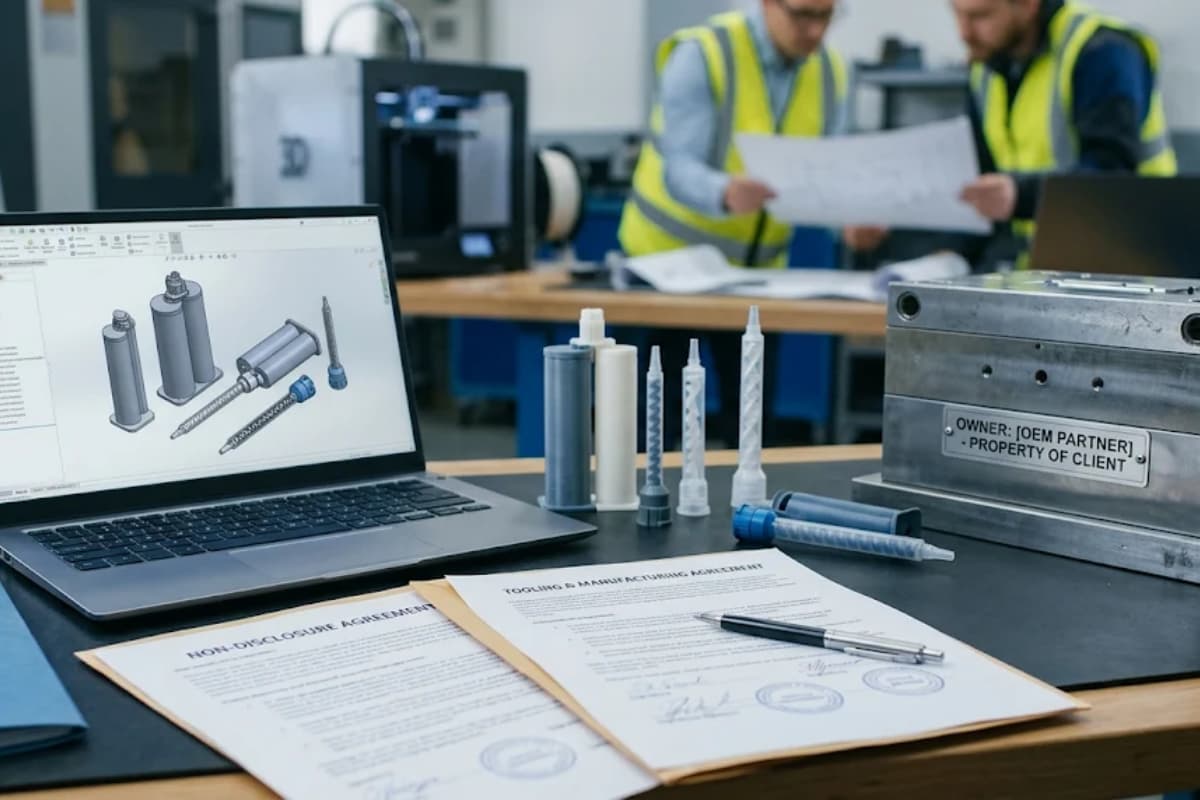
To qualify adhesive cartridge piston insertion, record force against insertion travel, check the final piston depth, and inspect the assembled seal. Establish limits using the actual barrel, piston, tooling and filling condition. A single maximum-force number leaves room for a piston to stop early, tilt, or damage a sealing lip while still passing the force check.
Packaging and quality engineers can use this method to qualify an already selected cartridge and piston. An assembly acceptance window describes the permitted force over defined parts of the stroke, together with the required final condition. A force limit is useful only when another inspector can reproduce the test.
Define the assembly condition before measuring force
An empty-barrel insertion test can help compare mechanical fit. A filled-cartridge test adds effects from the formulation, remaining air and venting sequence. Name the test condition on every trace. When comparing suppliers or lots, use the same condition and record any deviation before interpreting a force difference.
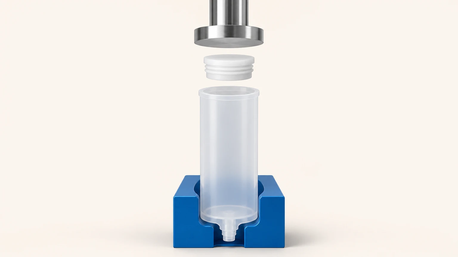
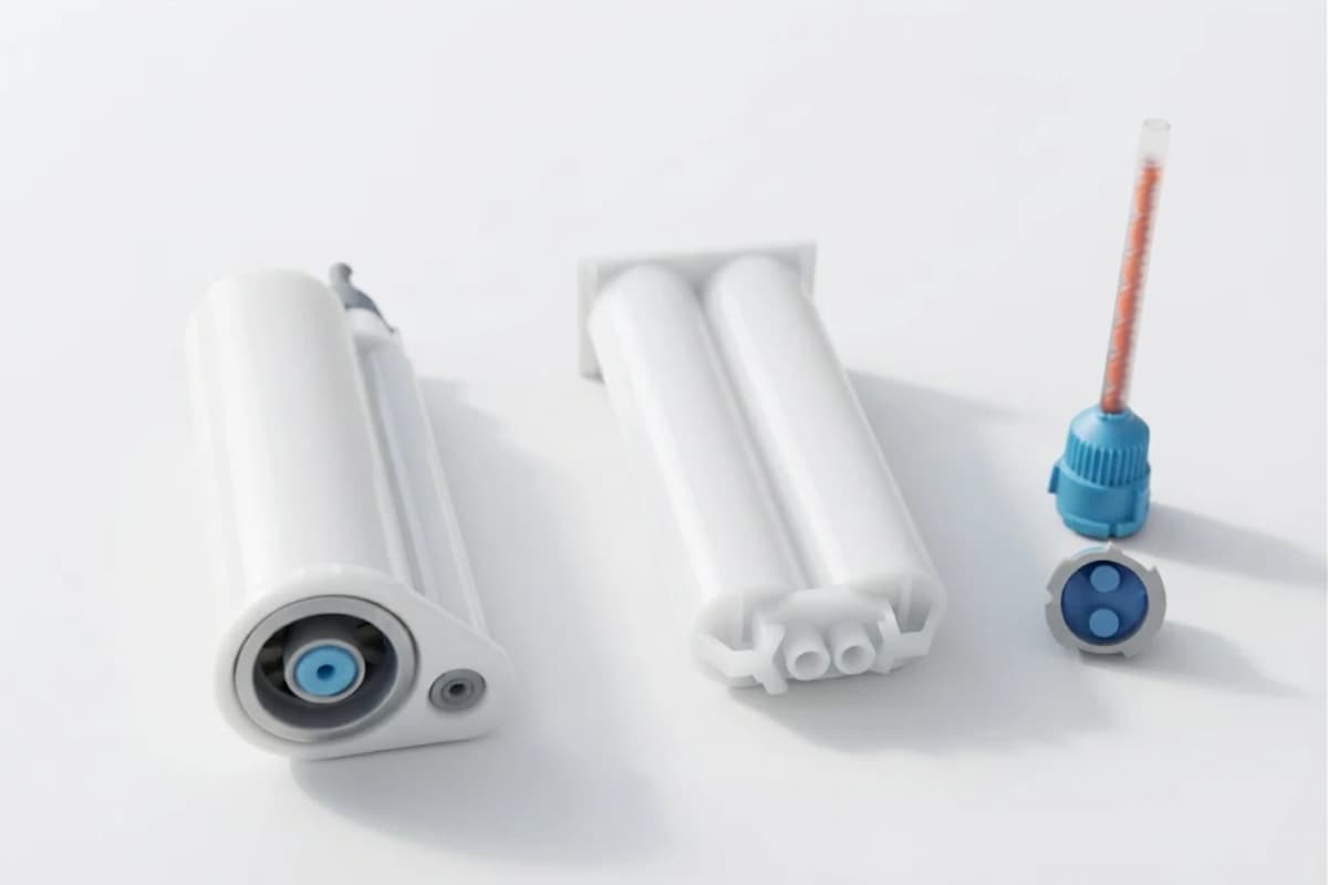
Venting is part of that definition. Nordson EFD offers air-free, center-bleed-plug and solid multi-seal piston designs, each with its own air-removal approach. Use the insertion and closing sequence specified for the chosen design. A change in piston type can change the appropriate tooling and test sequence. Nordson EFD 2K piston designs.
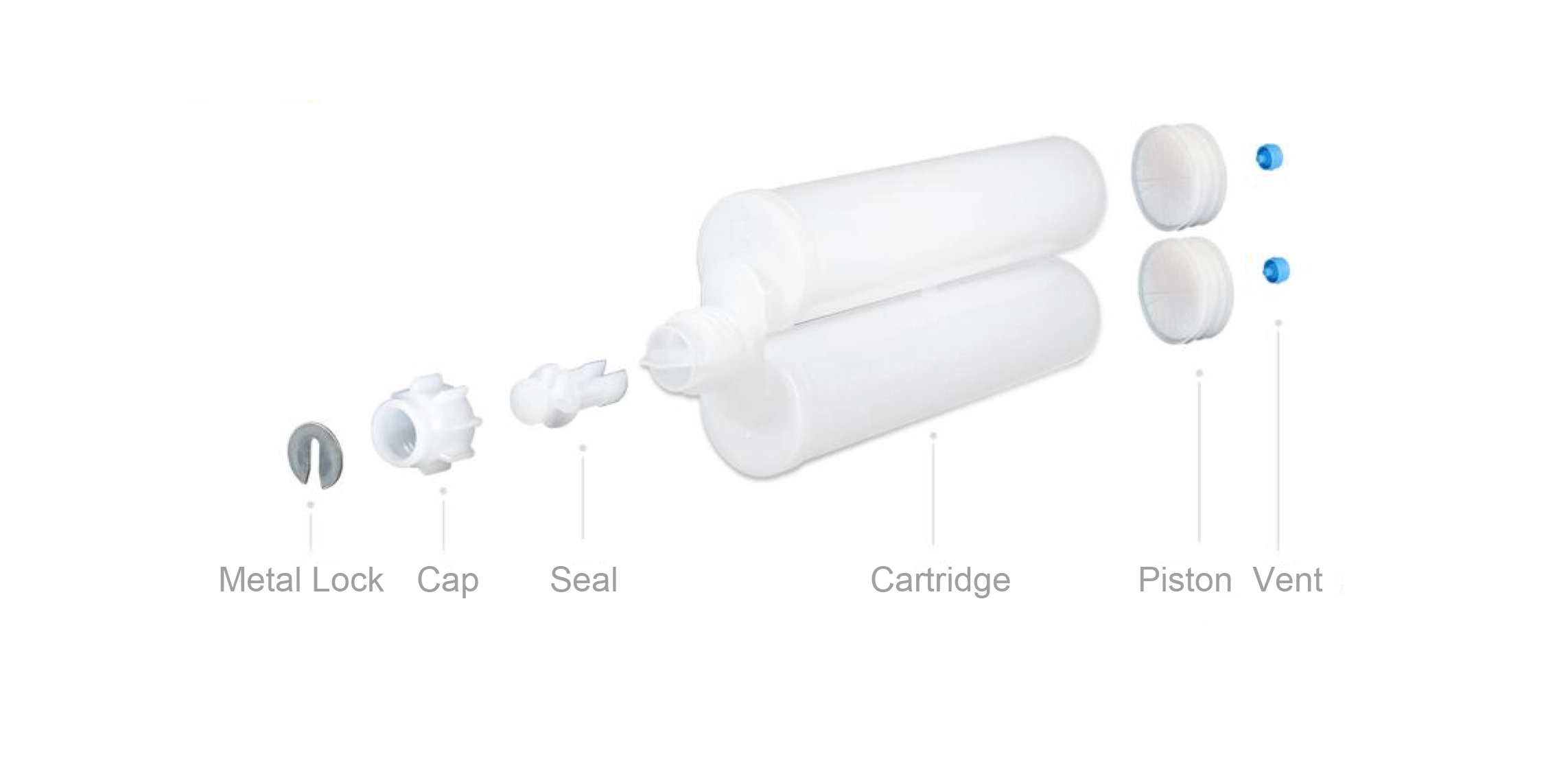
Before the first trial, put these inputs on the method sheet:
- Barrel and piston part numbers, revisions, material identification and lot or cavity marks where available.
- Empty or filled state, formulation and temperature, fill level, outlet closure, and any approved lubricant or surface treatment.
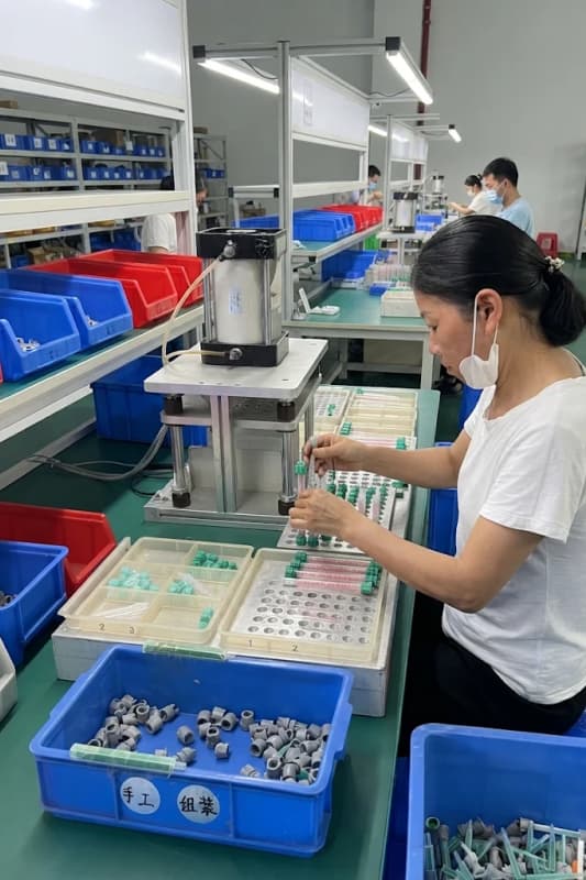
- Guide, insertion tip and support fixture identities, including the face that establishes the cartridge position.
- Insertion speed, any dwell, the displacement zero, final-depth datum and vent opening or closing sequence.
- Force and displacement sensor ranges, calibration status, sampling settings and the stop conditions that protect the sample and tooling.
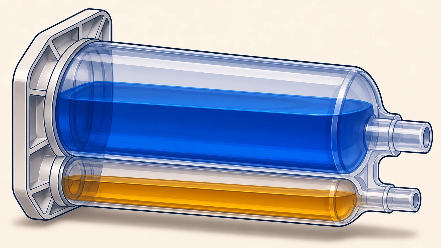
If the setup uses two insertion rods, record whether they move independently or share a crosshead. One load cell above both rods measures combined resistance. A normal total can hide a higher load on one side and a lower load on the other. Individual trials or separate sensing are needed when the acceptance requirement applies to each chamber.
Read the stroke in relation to the piston position
Plot force in newtons against travel in millimeters. Label where the piston first engages the barrel and where the approved insertion ends. The shape will depend on the assembly. It may include a short entry peak, a changing sliding region and a final seating event. Some designs have no distinct final peak.
Kistler describes assembly monitoring as the evaluation of force together with displacement. This supplies a useful principle for cartridge trials: a force value gains meaning when its position in the stroke is known. Kistler force-displacement measurement.
An unusually early rise should prompt a check of piston orientation, guide alignment and contact at the barrel entrance. A rise later in a filled trial may involve the liquid or the venting sequence. A sudden drop can have several explanations, including a slip or change in contact. Preserve the sample and examine it before assigning a cause from the trace alone.
Machine travel also includes any movement or deformation of the fixture and load train. Measure the installed piston position from a defined cartridge datum after unloading. That check can reveal an apparent full stroke caused partly by fixture deflection. Our cartridge dimensional inspection guide explains how to make those reference surfaces reproducible.
Run a trial that another inspector can repeat
- Check the fixture and measuring system. Verify alignment, support and the insertion tip against the method drawing. Zero the force channel under the specified starting condition. Use a suitable check artifact or reference procedure to verify force and travel before testing production samples.
- Establish the travel reference. Use the defined mechanical datum or contact trigger consistently. If a force trigger sets zero, record its threshold. A changed trigger shifts the curve horizontally and can make an unchanged assembly appear different.
- Insert once at the agreed speed. Capture the complete trace and keep the raw data. Stop at the validated end position or the protective limit. Record interrupted cycles as interrupted. Repeated insertion into the same barrel changes the contact history, so use fresh pairs when comparing first-assembly behavior.
- Inspect after unloading. Measure final depth and check for tilt, cracks, shaving, displaced lips and visible material past the intended sealing boundary. Follow the product-specific vent-closing procedure and include the functional seal check required by the qualification plan.
- Repeat across the relevant variation. Include the intended lots or molding cavities and the allowed process settings. Record sample identities so a later outlier can be traced to a component combination.
Select acquisition settings that resolve the shortest event you need to evaluate. Check that increasing the sample rate or reducing smoothing does not reveal peaks hidden by the original settings. Keep filtering consistent between qualification and production, and account for measurement uncertainty when setting acceptance near a limit.
medmix describes the risk of damaging sealing lips during piston setting and the need to coordinate vent closure with contact at the adhesive. That supports checking the completed assembly alongside the trace. The correct closing action remains specific to the piston design. medmix guidance on air-free filling and piston setting.
Build limits from verified assemblies and known defects
Start with samples whose final depth, physical condition and required sealing performance have been verified. Overlay their traces using the same displacement reference. Look for regions that are stable enough to evaluate, then propose force bounds for those regions and an independent depth requirement.
The observed minimum and maximum of a small sample provide a preliminary view of variation. Production limits also need allowance for normal variation, measurement uncertainty and the defects the check must detect. Keep a distinct protective stop limit for equipment and sample protection. That stop setting may serve a different purpose from the quality acceptance boundary.
Challenge the proposed window with identified abnormal samples in a controlled trial. For example, evaluate a documented shallow insertion or an intentionally misaligned setup within safe limits. Confirm the physical defect independently, then check whether the proposed rule detects it. If good and defective samples overlap, add an appropriate depth, vision or seal check and revise the process. Widening the force limits merely to clear alarms can let the same defect pass.
A passing peak can accompany a shallow piston
The following records are hypothetical and illustrate a decision rule. Assume a trial method specifies a peak force of 40–80 N in its defined entry region and a final piston-face depth of 12.0 ± 0.2 mm from the rear flange after unloading. The agreed sliding-region envelope and visual checks also apply. These values are invented for the example and require replacement by validated limits for the actual cartridge.
| Sample | Entry peak | Final depth | Disposition |
|---|---|---|---|
| A | 62 N | 12.1 mm | Pass these two checks. Complete the envelope, visual and seal checks. |
| B | 64 N | 11.3 mm | Hold. The piston is shallow despite the acceptable peak. |
| C | 91 N | 12.0 mm | Hold. Correct depth does not clear the excessive entry force. |
For B, inspect the trace endpoint, stop trigger, fixture seating and piston position before rerunning the process. For C, preserve the sample for inspection of the entry and sealing lips, and compare component identities and alignment. Force data alone cannot establish whether a lip was damaged. The piston seal evaluation guide covers the subsequent contact and bypass-leakage questions.
Record the affected lot and the inspection result against the original trace. Use the agreed sampling and containment plan to decide how far to extend the investigation. A failed sample does not quantify the defect rate of the entire lot, and a successful second push should not replace the first trace in the record.
Questions when transferring the method to production
Can the press pressure display replace a force sensor?
Only after validating how that reading relates to force at the piston under the actual setup. Cylinder pressure, actuator area, friction and tooling losses affect the relationship. A pressure setting by itself does not provide a measured insertion-force trace.
Does an empty-cartridge test approve a filled assembly?
It can qualify the stated mechanical test condition. A filled assembly needs evaluation with its specified formulation, temperature, fill level and venting sequence because those conditions can change the load and final piston position.