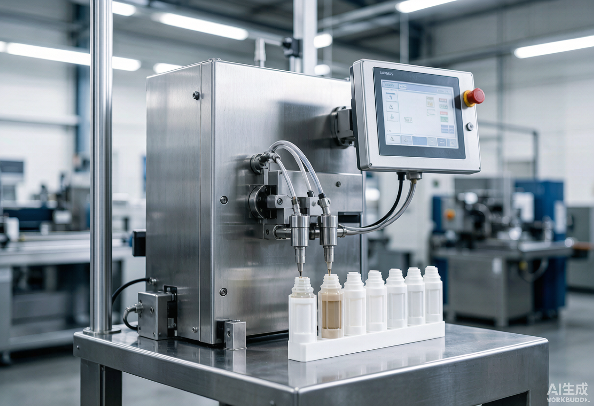
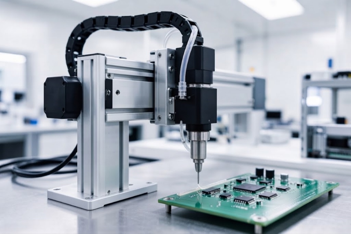
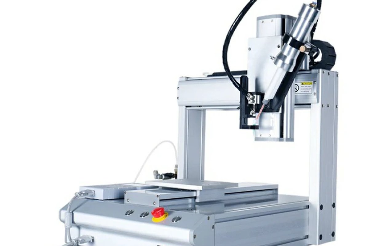
A cartridge filling machine is specified by four variables, not by machine size: whether the material is single or two component, the viscosity range at filling temperature, the cartridge sizes and mix ratios you must fill, and the true target output including piston insertion and capping. Once those four are fixed, the feed mechanism, the metering system and the automation level follow directly. This guide works through each variable, maps it to a machine configuration, and closes with a specification sheet you can send to a supplier.
The Four Variables That Decide Your Machine Configuration
Most sourcing mistakes on cartridge filling equipment come from starting with a machine model instead of a process definition. Buyers ask for “a 400 ml cartridge filling machine” when the real constraints are viscosity, ratio and changeover frequency. A machine that fills 400 ml at 5,000 mPa·s will not behave the same way with a 400 ml cartridge filled at 500,000 mPa·s, and a line that switches between three sizes twice a shift needs a different changeover design than a line that runs one size for a week.
The four variables, in the order they should be answered:
- Component count: single component (1K) or two component (2K).
- Viscosity of each component at filling temperature.
- Cartridge format: size range, material, piston type, and for 2K the mix ratio.
- Required output: filled cartridges per minute, counted with all steps included.
Everything else — tank volume, heating, PLC, footprint, power — is downstream of these four.
Viscosity Sets the Feed Mechanism, Not Just the Motor
Viscosity is the single most common reason a filling machine fails in the field. If material cannot reach the fill nozzle at a stable rate, the machine will either under-fill, leave headspace that becomes trapped air, or stall the cycle.
| Viscosity band at filling temperature | Feed mechanism required | Effect on machine design | Reference model |
|---|---|---|---|
| 100–20,000 mPa·s (1K) | Tank to pump feed | Standard tank-fed filling, optional tank heating | DH-F002, DH-F009, DH-AF016 |
| 1,000–20,000 mPa·s (2K) | Dual tank with metered delivery | Two independent tanks, ratio control, optional heating | DH-F001-400-50 |
| 5,000–1,000,000 mPa·s (1K) | Compression plate (ram) | High-force plate presses material into the cartridge | DH-F003 |
| 10,000–1,000,000 mPa·s (2K, 10:1) | High-viscosity 2K metering | Reinforced frame, larger drive, twin heated tanks | DH-F005-5010 |
Why the compression plate matters above roughly 5,000 mPa·s
Pump-fed filling relies on material flowing into the pump inlet. As viscosity rises, the material stops following the pump and the fill weight drifts. A compression plate removes the flow problem by mechanically pressing the product out of its original container, which is why a compression plate machine handles a viscosity band that a standard pump-fed unit cannot.
This also explains a specification detail buyers often overlook: DH-F003 accepts 20 cc to 75 cc cartridges, the same size range as DH-F002, but covers a completely different viscosity band. The cartridge list looks identical; the machines are not interchangeable.
Temperature is part of the viscosity specification
Viscosity is meaningless without a temperature. A sealant that measures 800,000 mPa·s at 20 °C may fall into a pumpable range when conditioned. Both DH-F002 and DH-F005-5010 offer optional glue tank heating for this reason. Always state the filling temperature when you send viscosity data to a supplier, and confirm whether the quoted machine includes tank heating or offers it as an option.
1K vs 2K: Two-Component Filling Adds Ratio Control and Piston Sequencing
A single component cartridge filling machine fills one material into one barrel and then places a piston or cap. A two component cartridge filling machine has to deliver two materials in a defined ratio, into two separate barrels of the same cartridge, without cross-contamination and without entraining air — and then place pistons in both barrels.
That difference drives four additional requirements:
- Ratio accuracy: the machine must hold the stated ratio across the whole fill. DH-F001-400-50 covers 1:1, 2:1, 4:1 and 10:1; DH-F005-5010 is configured for 10:1.
- Independent material paths: two tanks, two metering routes, and a cleaning procedure for each.
- Piston handling: both barrels need pistons seated at the correct depth. DH-F005-5010 is built as one filling station plus two piston assembly stations, which reflects how much of the cycle time piston placement consumes on high-viscosity 2K products.
- Shelf-life separation: for reactive systems, the resin and hardener must not meet until dispensing, so the fill path design matters as much as the fill accuracy.
If you are still deciding between 1K and 2K packaging for a product line, it is worth reading a packaging comparison before specifying the machine, because the packaging decision fixes the machine architecture for years.
Matching Cartridge Sizes and Changeover to Your Product Mix
Published speed figures assume one size, one material and a trained operator. Real lines rarely work that way. The table below lists the published configuration of each model so you can see where a single machine covers your size range and where you would need separate tooling.
| Model | Components | Cartridge sizes | Mix ratio | Published speed | Viscosity range | Machine size | Power |
|---|---|---|---|---|---|---|---|
| DH-F001-400-50 | 2K | 50 / 75 / 200 / 250 / 400 / 490 ml | 1:1, 2:1, 4:1, 10:1 | 5–15 cartridges/min | 1,000–20,000 mPa·s | L1100 × W900 × H1300 mm | 3 kW |
| DH-F002 | 1K | 20 / 30 / 50 / 75 cc | — | 5–30 cartridges/min | 100–20,000 mPa·s | L1100 × W700 × H1000 mm | 0.5 kW |
| DH-F003 | 1K | 20 / 30 / 50 / 75 cc | — | 5–30 cartridges/min | 5,000–1,000,000 mPa·s | L1000 × W700 mm | 0.5 kW |
| DH-F005-5010 | 2K | 50 / 75 / 250 / 490 ml | 10:1 | 5–10 cartridges/min | 10,000–1,000,000 mPa·s | L1200 × W1300 × H1600 mm | 3 kW |
| DH-F009 | 1K, table-top | 1 / 10 / 20 / 30 / 50 / 75 cc | — | 5–10 cartridges/min | 100–20,000 mPa·s | L500 × W400 × H1000 mm | 0.2 kW |
| DH-AF016 | 1K, fully automatic | 10 / 20 / 30 / 50 / 75 cc | — | 8–10 cartridges/min | 100–20,000 mPa·s | Confirm with supplier | Confirm with supplier |
Values are published model data. Confirm the current configuration, tooling set and utilities before ordering, because optional items such as tank heating, capping and piston feed change both price and layout.
Two patterns stand out. First, DH-F001-400-50 supports two different cartridge sizes on one machine, which suits converters that run a small and a large format from the same material pair. Second, DH-F009 is designed to fill from a small opening with the piston pre-assembled, and accepts an original pack size under 1 L — that configuration exists for producers who fill directly from small original containers rather than from a bulk tank.
Output Planning: What “Cartridges per Minute” Really Includes
Speed figures are the most frequently misread number in a filling machine quotation. Ask every supplier which of the following are inside the quoted cycle:
- Cartridge loading, manual or automatic
- Fill time itself
- Piston insertion
- Capping or cap placement
- Discharge to the next station
- Operator handling between cycles
A machine rated at 5–15 cartridges per minute with manual loading and manual piston placement will not hold that rate across a full shift unless the operator station is laid out for it. DH-AF016 adds automatic material feeding, piston assembly, small-opening filling and capping in one machine, which is precisely the set of steps that otherwise consume operator time.
A practical way to plan: take your monthly volume, divide by realistic shift minutes with an operator efficiency factor, and only then compare against the published range. If your requirement sits near the top of a machine’s published range permanently, specify the next configuration up rather than running the machine at its limit every day.
Filling Quality Risks: Air, Ratio Drift, and Piston Placement
Three defects account for most complaints on filled cartridges, and each one maps back to a machine setting.
| Defect | Typical root cause | Where it is controlled |
|---|---|---|
| Air pockets in the cartridge | Fill speed too high, material dropping into the barrel, no de-aeration step | Fill nozzle design, fill profile, optional vacuum filling |
| Off-ratio 2K product | Metering drift, temperature change between the two components, partial blockage in one path | Twin tank temperature control, ratio verification, cleaning routine |
| Piston seated at the wrong depth | Piston insertion force or stroke not matched to cartridge and material | Piston assembly station setting, DH-F001 and DH-F005 piston functions |
Vacuum filling is a separate process decision with its own trade-offs. If your material traps air easily, or if you fill directly into cartridges used for structural bonding, it is worth comparing vacuum and conventional filling before finalising the machine specification.
Semi-Automatic vs Fully Automatic: Labour, Feeding and Capping
The automation decision is a labour and consistency decision, not a prestige decision.
Semi-automatic benchtop units such as DH-F009 suit pilot runs, sample production and low-volume speciality products. The capital exposure is low, and changeover between sizes is quick.
Floor-standing semi-automatic machines such as DH-F002 and DH-F003 suit established production with a dedicated operator, where the same sizes run for long stretches.
Fully automatic configurations such as DH-AF016 suit lines where the filling cell has to keep pace with upstream or downstream equipment, or where labour cost per cartridge is the dominant variable. Automatic feeding and capping remove two manual steps, but they also add changeover work when the cartridge format changes.
If your product mix changes weekly, a simpler machine with fast changeover usually produces more saleable cartridges per month than an automated cell that spends its time being re-tooled.
Utilities, Footprint and Integration Checklist
Before the machine is ordered, confirm the following against your plant:
- Compressed air: the models listed above are specified at 0.4–0.7 MPa. Confirm your supply holds that range at the machine inlet under load.
- Electrical supply: power ratings range from 0.2 kW on the table-top unit to 3 kW on the 2K machines. Confirm voltage and phase.
- Control platform: DH-F001, DH-F002, DH-F003 and DH-F005-5010 use Siemens PLC and HMI; DH-F009 uses PLC and HMI. Confirm whether your maintenance team needs training on the platform.
- Floor space and service access: DH-F005-5010 occupies L1200 × W1300 × H1600 mm, which is a different class of installation from the L500 × W400 mm table-top unit. Allow space for tank loading and cleaning access, not just the machine outline.
- Tank volume versus batch size: DH-F001 uses two 30 L tanks and DH-F005-5010 uses two 20 L tanks with optional heating. Match tank volume to your batch size so that material is not sitting in the tank beyond its working life.
- Consumable compatibility: the machine, the cartridge and the pistons must be specified together. Cartridge body material and piston design affect sealing and plunger force during filling.
A Seven-Question Specification Sheet to Send to Suppliers
Copy this into your enquiry. Answers to these seven questions produce a comparable quotation from any supplier.
- Is the product single component or two component, and what is the mix ratio for 2K?
- What is the viscosity of each component, and at what temperature was it measured?
- Which cartridge sizes, materials and piston types must the machine handle?
- What output do you require, in filled cartridges per shift, with pistons and caps included?
- How often does the format change, and how long can changeover take?
- What are the available compressed air, power and floor space?
- Which steps must be automatic: feeding, filling, piston placement, capping, discharge?
Add material safety data and, where possible, a sample cartridge. Most configuration errors are found on a filling trial, not on a datasheet.
Key Takeaways
- Specify the process first: component count, viscosity, cartridge format and true output decide the machine, not the model name.
- Viscosity determines the feed mechanism. Above roughly 5,000 mPa·s, plan for a compression plate or a high-viscosity 2K metering design rather than a standard pump-fed unit.
- 2K filling adds ratio control, dual material paths and dual piston handling, which is why 2K machines are larger and slower per cartridge than 1K machines of the same size range.
- Published cartridges-per-minute figures assume a stable format and trained operator; subtract piston insertion, capping and handling before you plan capacity.
- Air entrapment, ratio drift and piston depth are the three defects to design out, and each traces back to a specific machine setting.
- Confirm utilities early: 0.4–0.7 MPa compressed air, 0.2–3 kW power depending on model, and floor space that includes tank loading and cleaning access.
Frequently Asked Questions
What is the difference between a single component and a two component cartridge filling machine? A single component machine fills one material into one barrel and then places a piston or cap. A two component machine meters two materials in a fixed ratio into two barrels of the same cartridge, keeps the two paths separate until filling, and places pistons in both barrels. The 2K machine therefore requires dual tanks, ratio control and a more involved cleaning routine.
Can one cartridge filling machine handle different cartridge sizes? Some can. DH-F001-400-50 is built to support two different cartridge sizes on one machine and covers 50, 75, 200, 250, 400 and 490 ml. Most machines require a tooling or format change between sizes, so confirm the changeover time and the tooling included in the quotation.
What viscosity can a cartridge filling machine handle? It depends on the feed mechanism. Pump-fed models in this range are specified for 100–20,000 mPa·s. The compression plate model DH-F003 is specified for 5,000–1,000,000 mPa·s, and the high-viscosity 2K model DH-F005-5010 for 10,000–1,000,000 mPa·s. Always state the measurement temperature.
How fast can a cartridge filling machine run? Published rates for this range run from 5–10 cartridges per minute on high-viscosity 2K configurations up to 5–30 cartridges per minute on low-viscosity single component machines. Rates depend on cartridge size, fill volume, viscosity and how much of the cycle is manual.
Do I need vacuum filling? Vacuum filling is used where trapped air causes quality problems, for example structural adhesives and sealants where bubbles become voids in the bond line. Whether you need it depends on the material and the application; both conventional and vacuum approaches have trade-offs in cycle time and cost.
What information should I send to get an accurate quotation? Component count and ratio, viscosity with temperature, cartridge sizes and materials including piston type, required output per shift, changeover frequency, available air and power, and which steps must be automatic. A filled sample cartridge speeds up the trial considerably.
Next step — Send Haijing your material viscosity, cartridge sizes and target output, and the application team will recommend a filling configuration and arrange a filling trial with your material.