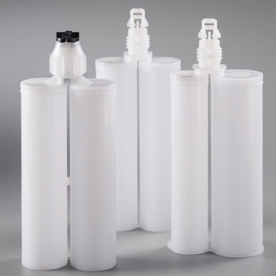
An automated adhesive dispensing system does not need an articulated robot to be production-ready. If the part sits in a repeatable fixture and the outlet can reach every point with straight X, Y, and Z moves, a dedicated coordinate dispenser is usually the cleaner choice. A SCARA can cover the middle ground when jointed horizontal reach helps but the outlet remains mainly vertical; choose a six-axis robot only when the process truly needs changing tool orientation, reach around obstructions, several part faces, or part handling.
In short: stabilize the complete adhesive dispensing system first: material supply, ratio, mixer, valve, and cutoff. Then buy the least complex motion platform that can execute the validated path. A robot adds reach and orientation; it does not repair unstable flow, an incorrect component ratio, poor mixing, or inconsistent fixtures.
Key Takeaways
- A robot is not the whole system. Material supply, metering, mixing, cutoff, controls, and inspection still determine deposit quality.
- Use Cartesian motion for constrained paths. Stable fixtures and top-down access rarely justify articulated axes.
- Screen SCARA before six-axis motion. Jointed horizontal reach can suit compact, mainly vertical dispensing without full three-dimensional reorientation.
- Use articulated motion for orientation. Multi-face beads, angled joints, obstructions, and part handling can justify a robot.
- Fix part presentation before adding axes. A better datum or fixture can remove motion complexity and simplify commissioning.
- Treat a cobot as a robot application. The complete task still needs a documented risk assessment and suitable risk reduction.
- Release evidence, not promises. Approve startup, steady running, corners, pauses, restarts, cure, alarms, and changeover behavior.
The Short Answer for Buyers
Choose a dedicated coordinate dispensing system when the tool can stay in one orientation and the part arrives at a known datum. The common case is a flat or shallow assembly held in a fixture while an outlet follows dots, lines, arcs, or fills inside an orthogonal work envelope. The fewer moving relationships you create, the easier the process is to teach, inspect, and restore after maintenance.
Choose an articulated industrial robot when the nozzle must approach from different angles, travel around features, follow several faces, or reach a large three-dimensional part. A robot can also carry a lighter component beneath a fixed applicator. That layout reduces hose movement when moving the part is easier than moving the dispensing hardware.
A collaborative robot belongs in the articulated branch, but “collaborative” describes capabilities used in a risk-controlled application. It does not prove the adhesive, outlet, fixtures, moving part, or programmed task is safe. Select it for a validated interaction model, not because the word sounds easier.
Compare the Two Motion Architectures
The table is the fast decision view. The sections below explain the trade-offs that a quotation cannot show.
| Decision | Coordinate Workstation | SCARA | Six-Axis Robot or Cobot | Best Fit |
|---|---|---|---|---|
| Tool orientation | Usually fixed | Mainly vertical approach | Changes through the path | Six-axis for angled access |
| Work envelope | Orthogonal and bounded | Jointed horizontal reach | Three-dimensional and jointed | Coordinate for flat work |
| Part presentation | Repeatable fixture preferred | Compact fixtured cell | More reach around variation | Fix the datum first |
| Product changeover | New fixture and program | New tooling and path | New tooling, path, and risk review | Compare complete changeover |
| Dispense hardware | Still required | Still required | Still required | No motion advantage |
| Cell integration | Narrower control boundary | Intermediate motion boundary | Broader safety and interface boundary | Coordinate when sufficient |
Do not score architectures by axis count alone. Score the complete application: part loading, fixture repeatability, outlet access, hose routing, material replenishment, recipe control, alarms, inspection, cleaning, and safe service access. An extra axis can solve one reach problem while creating a maintenance or validation problem elsewhere.
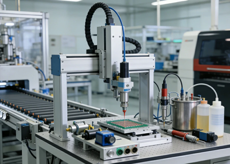
Nordson describes one current XYZ product as an automated three-axis benchtop dispensing system with a gantry-mounted meter. Henkel lists three-axis benchtop and rotary configurations in its robotic dispensing range. These products show why “robot” is a broad label. The engineering question is the motion architecture, not the marketing category.
Define Each Automation Boundary Clearly
A coordinate applicator controls the position and timing of a dispense outlet inside a defined machine frame. The fluid source may be a syringe, single cartridge, dual cartridge, pressure vessel, or metering unit. The motion controller can trigger the valve or drive, yet the fluid path remains a separate subsystem with its own compatibility and maintenance limits.
A SCARA sits between an orthogonal stage and a six-axis arm. FANUC describes its joint-controlled X-Y motion and lists dispensing among common SCARA applications. Treat SCARA as a candidate when the cell benefits from jointed horizontal reach and a compact footprint while the outlet still approaches mainly along a vertical axis. If the tool must pitch or roll through the bead, the reach study should move to six-axis motion.
An articulated robot replaces the orthogonal motion stage with a jointed arm. The arm may carry the valve over a fixed part, or it may carry a lighter part beneath a stationary valve. FANUC documents both carried-dispense and pedestal-dispense layouts. The second option can reduce hose movement, but it transfers payload, grip, and part-datum responsibilities to the robot.
Neither boundary decides how a two-component adhesive maintains ratio or becomes homogeneous. A 2K process still needs separated component paths, compatible outlets, controlled proportioning, and an approved mixer. Motion begins after those functions are stable enough to follow a path.
Freeze these subsystem boundaries before requesting quotes:
- Fluid boundary — package, feed, ratio, mixer, valve, outlet, and cleaning method.
- Motion boundary — fixture, axes, tool orientation, path, speed profile, and cable routing.
- Control boundary — recipes, triggers, interlocks, alarms, sensors, and production records.
- Acceptance boundary — deposit, cure, inspection method, changeover, and release owner.
Choose Motion From Path Geometry
Draw the outlet path before selecting the machine. Mark every start, stop, corner, height change, obstruction, and required tool angle. Include the loading position and the space needed to remove the mixer or clean the valve. A path that fits on a screen can still fail when the physical outlet cannot reach a service point.
Flat and Top-Down Paths
PCBs, flat covers, shallow housings, trays, and repeated dots often suit coordinate motion. The part fixture provides the datum, and the outlet approaches from one direction. A rotary fixture can add a circular or indexed move without buying a fully articulated arm. This architecture wins when orientation does not change.
Multi-Face and Angled Paths
A robot earns its complexity when the outlet must stay normal to changing surfaces, follow a sidewall, enter a recessed joint, or move around tall features. Large structural parts can also exceed a practical benchtop envelope. These are geometric reasons. “Future flexibility” alone is not one.
Move the Tool or Part
If the dispenser is heavy or its hoses resist fast reorientation, fix the applicator and let the robot present a lighter component. If the part is large, delicate, or difficult to grip, fixture it and move the outlet. The correct choice minimizes the mass, hose movement, and datum changes that the path must control.
| Path Condition | First Choice | Escalate When |
|---|---|---|
| Flat dots or beads | XYZ coordinate stage | Tool angle must change |
| Circular seal | Rotary or XYZ fixture | Circle lies on several faces |
| Recessed sidewall | Articulated robot | Coordinate access is blocked |
| Large fixed structure | Robot carries outlet | Reach study confirms access |
| Small movable part | Fixed valve plus robot | Grip preserves the datum |
Part variation deserves its own decision. A robot can offset a path from measured datums, but programming around warped or poorly located parts may hide an upstream process problem. Repair the fixture or incoming part condition when that is the true cause. More motion cannot create a stable reference.
Stabilize Fluid Delivery Before Motion
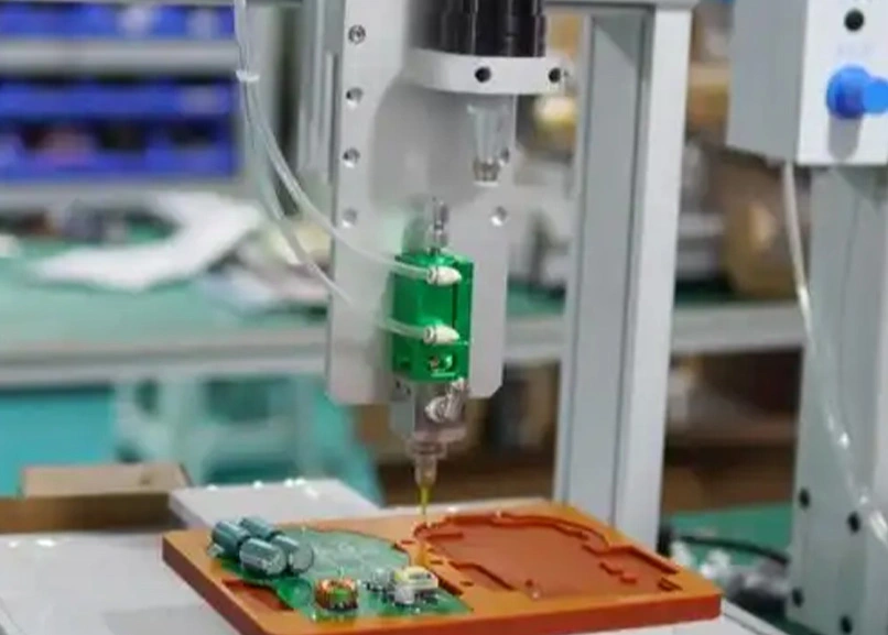
An automated epoxy dispensing system has two coupled control problems. The fluid system determines what exits the outlet; the motion system determines where and when it lands. Debug them separately before combining them. Otherwise, a narrow bead at a fast corner could come from path speed, pressure response, ratio drift, mixer restriction, or a partial blockage.
Start with the approved cartridge system. Haijing documents dual-component cartridge formats from 50 to 1500 ml across the portfolio, with 1:1, 2:1, 4:1, and 10:1 configurations. Those figures describe available families, not universal interchangeability. The cartridge outlet, gun or drive, mixer inlet, and component ratio must match the selected drawing.
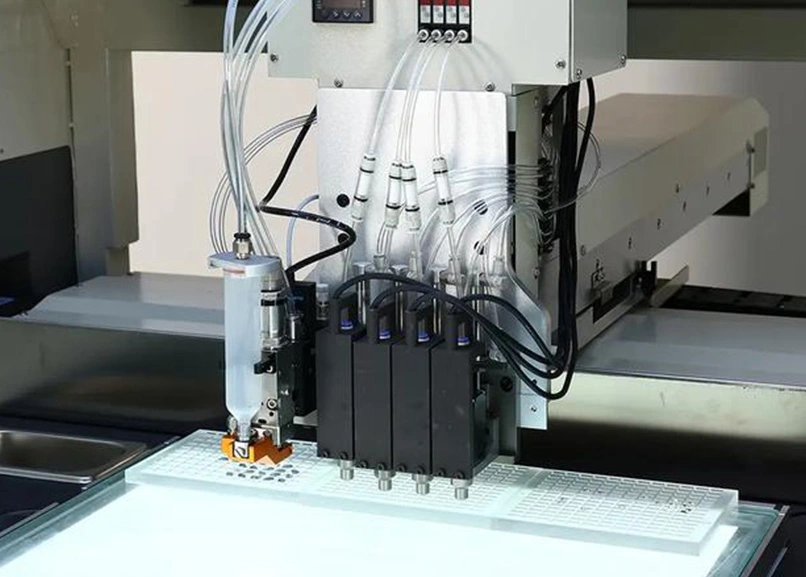
Static mixers and dynamic mixers solve different material and process conditions. Static mixers use the energy already present in the moving streams. Dynamic mixers add driven rotation and are documented in Haijing’s machine-use portfolio for ratios as high as 100:1. The larger number does not make dynamic mixing the default. Use it only after the material and process justify the added drive, controls, cleaning, and maintenance boundary.
Integrated controls can coordinate the two subsystems. ABB’s dispensing package adjusts flow with robot speed and monitors dispensed volume. That is a named product capability, not a universal robot feature. Require the proposed supplier to show exactly which command, feedback, and alarm signals cross the motion-fluid interface.
Compare Changeover and Integration Work
High-mix production changes the answer. A coordinate workstation can be fast to restore when each product has a controlled fixture, outlet height, and recipe. An articulated platform can cover more orientations, but every new job may also change the end-effector, hose posture, collision envelope, safety assessment, and inspection plan.
Dedicated production favors a narrow machine boundary. The cell repeats one material package, one fixture family, and one path class for long runs. Flexible production favors reusable motion and recipes, provided the changeover record controls every fluid-contact part. A saved robot path is not a complete adhesive recipe.
| Change Item | Coordinate System | Robot or Cobot | Required Record |
|---|---|---|---|
| New part | Fixture and program | Toolpath and collision check | Approved datum map |
| New adhesive | Review every wetted component | Compatibility and cure evidence | |
| New cartridge ratio | Match drive, outlet, and mixer | Controlled component list | |
| New outlet | Re-teach height | Re-teach tool center point | Outlet drawing and offset |
| New cycle target | Recheck flow and path together | Updated acceptance run | |
Integration effort lives in interfaces. List the PLC handshake, part-present signal, recipe selection, material-low input, cycle-permit logic, purge command, reject response, and production record before awarding the project. If two suppliers split motion and dispensing, name who owns the synchronized trial. Unowned interfaces become commissioning delays.
Close the maintenance boundary before production release:
- Motion platform and controller — name the owner of program backups, recovery procedures, limits, and controller diagnostics.
- End effector and hose dress — assign tooling drawings, offsets, cable routing, wear checks, and collision-recovery approval.
- Fluid hardware — assign cartridge or reservoir service, drive, valve, mixer, outlet, purge, and wetted-component compatibility.
- Critical spares — freeze approved part numbers, supplier lead times, shelf-life or storage limits where applicable, and the stock needed to stay inside the project’s tolerated stop.
- Changeover consumables — document which mixers, tips, seals, and cleaning items must be available before a recipe is released.
There is no universal spare quantity for every cell. Set stock from the approved configuration, failure consequence, replenishment time, storage constraints, and the production stop the site can tolerate. A substitute that changes the fluid path or tool offset requires review before use.
Need to Prove the Fluid Path First?
If you are selecting a cartridge-fed 1K or 2K process, send the adhesive package, component ratio, proposed path, and target cycle. Haijing can help identify compatible cartridges, mixers, guns, tips, or coordinate-applicator components for a production-representative trial.
Interfaces | Samples | Drawings
Treat Safety as Application Engineering
Robot safety belongs to the complete application. ISO currently lists ISO 10218-1:2025 for industrial robots and ISO 10218-2:2025 for industrial robot applications and cells. The distinction matters: buying a compliant robot does not complete the integration assessment for the cell, tool, material, fixture, and task.
A collaborative robot can support human interaction modes, but the end effector may still present pinch, puncture, chemical, pressure, or hot-surface hazards. The Association for Advancing Automation states that end users and integrators must assess the complete robotic application. Guarding, separation, speed limits, and other measures follow that assessment; the product label does not choose them.
Include these tasks in the application review:
- Production motion — normal paths, starts, stops, recovery, and foreseeable access.
- Material service — cartridge changes, refilling, purging, cleaning, and pressure release.
- Tool service — mixer replacement, needle handling, valve cleaning, and blocked-outlet recovery.
- Fault response — misloaded parts, lost datum, leaks, drips, alarms, and rejected deposits.
A dedicated enclosed workstation may offer a simpler boundary for a repetitive task. A robot or cobot may fit better where operators must load diverse parts or the path needs articulated access. Neither architecture is inherently safe for every adhesive application. Confirm current requirements with the machine builder, integrator, and relevant authority for the installation location.
Use This Eight-Question Decision Gate
Answer the questions in order. Stop at the first answer that changes the architecture, then validate it with a reach study and material trial.
| Question | If Yes | If No |
|---|---|---|
| Is the fluid path stable? | Continue | Fix dispensing first |
| Is the part datum repeatable? | Continue | Fix fixture or sensing |
| Can one tool angle reach all deposits? | Favor coordinate or SCARA motion | Study six-axis motion |
| Are all paths inside one orthogonal envelope? | Favor coordinate motion | Continue the reach study |
| Would jointed X-Y reach with a mainly vertical approach solve access? | Study SCARA | Study six-axis reach |
| Must the machine handle the part? | Study fixed-valve layout | Keep part fixtured |
| Will jobs change frequently? | Compare full changeover | Favor dedicated simplicity |
| Is the safety concept validated? | Proceed to trial | Stop architecture release |
The first two questions are gates, not scoring criteria. Do not use additional axes to compensate for unstable adhesive delivery or uncontrolled part location. Questions three through seven select motion and layout. The final question can block every choice until the application risk assessment is complete.
Walk Through a Bounded Selection Scenario
Illustrative input, not a customer case: a team plans to dispense a two-component adhesive from a 400 ml, 2:1 cartridge onto a rectangular cover. The bead sits on one top-facing plane, the cover locates against fixed datums, and operators load one part family. The values demonstrate the method; they do not approve a specific cartridge, gun, mixer, or machine.
First architecture: select a coordinate workstation for the initial trial. It can hold one outlet orientation and follow the required top-down path without articulated joints. The fluid trial must still match the exact 2:1 cartridge outlet, drive, mixer inlet, element geometry, and tip.
Change trigger: if a later product adds a vertical side bead behind an obstruction, repeat the reach study. That new geometry may justify a robot. Do not buy the robot early on the assumption that the second product will exist or that the same dispensing stack will transfer unchanged.
Run the stationary dispense checks before programming the rectangle. Confirm startup purge, steady output, cutoff, pause, restart, and cure using production-representative material. Then teach straight sections and corners, recording the path settings that produce the accepted bead. This sequence keeps motion changes from masking fluid changes.
Freeze the approved configuration as one controlled set: cartridge drawing, ratio, drive, mixer, outlet, fixture revision, program revision, material lot condition, and inspection method. A compatible-looking replacement can change restriction, tip offset, retained material, or purge behavior. Revalidate changes that can affect the deposit.
Specify Evidence Before Production Release
A supplier demonstration proves that equipment can move and dispense. Production release needs evidence that the complete process remains acceptable through the events operators will create every shift. Build the test around those events, not around one perfect bead on a clean sample plate.
Use production-representative material and parts to test:
- Startup — record purge condition and the first accepted deposit.
- Steady run — inspect output after the process reaches a repeatable state.
- Path transitions — check starts, stops, corners, height changes, and speed changes.
- Pause and restart — reproduce planned and unplanned stops within the approved window.
- Changeover — replace the controlled consumables and restore the process from the work instruction.
- Cure and traceability — connect the deposit result to material, recipe, program, and inspection records.
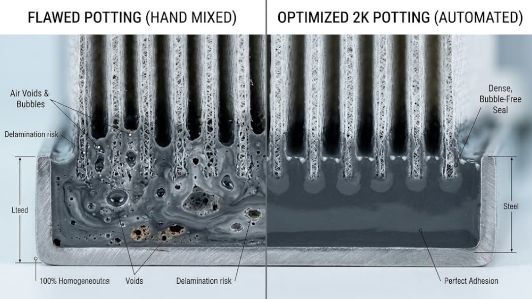
Measure what the product needs. A bead process may use width, height, location, continuity, mass, or cure evidence; a potting process may use fill mass, coverage, void inspection, or cure evidence. The article cannot set universal limits because the joint, adhesive, substrate, and equipment determine them. Put the project limits in the acceptance record.
Link alarms to decisions. A material-low input should define whether the current part completes, stops, or becomes suspect. A missed part-present signal should block the cycle. A flow or volume alarm should identify the affected production interval. An alarm that creates no containment action is only a screen message.
Source the Stack and Decide
Haijing supplies coordinate applicators and the component stack around cartridge-fed adhesive dispensing: single- and dual-component cartridges, A-, B-, C-, and F-System static mixers, machine-use dynamic mixers, manual and pneumatic guns, and dispense tips. The correct set starts with the exact adhesive package and drawing. Product-family names alone do not prove interface compatibility.
The documented sample route has no MOQ, while sample and freight fees apply and the listed lead time is 3–7 days. Available supporting files include test reports, FAI reports, STEP or IGES models, and chemical-compatibility tables. Ask for the documents that match the parts under review; availability does not make every document applicable to every SKU.
For the motion decision, bring the path drawing, fixture concept, required tool angles, part mass, proposed cell layout, utilities, control handshake, inspection method, and safety concept. For the fluid decision, bring the adhesive technical data, package, ratio, deposit, duty pattern, pause history, and cleaning limits. One missing input can invalidate an otherwise polished proposal.
Why We Write This Comparison
Haijing manufactures adhesive packaging and dispensing components, so our useful boundary is the interface between material package, drive, mixer, outlet, and automation. We do not claim that one motion platform is universally faster, more accurate, or less expensive. Those answers belong to the selected models and the production trial.
Our position is narrower: motion complexity should enter only after the fluid process and part datum are stable. That sequence gives integrators a cleaner specification and gives buyers evidence they can compare across proposals. It also prevents a robot from becoming an expensive workaround for a cartridge, mixer, fixture, or control problem.
References:
- Nordson — Meter Series XYZ Tabletop Robot.
- ABB — Integrated Dispensing Function Package.
- FANUC America — Robotic Dispensing and Sealing Systems.
- FANUC America — SCARA Robots.
- Henkel Adhesives — Automated Robotic Solutions.
- ISO — ISO 10218-1:2025 and ISO 10218-2:2025.
- Association for Advancing Automation — Collaborative Robot Safety.
Frequently Asked Questions About Automation
Is an automated adhesive dispensing system the same as a robot?
No. The system includes material supply, metering or ratio control, mixing, valve, controls, and inspection. A robot or coordinate stage supplies motion inside that system.
When is a Cartesian dispensing system the better choice?
Choose it when the part is presented repeatably and the outlet can reach every deposit with orthogonal X, Y, and Z motion while keeping one tool orientation.
When does adhesive dispensing need a six-axis robot?
Use articulated motion when the outlet must change orientation, reach several faces, follow complex three-dimensional geometry, work around obstructions, or handle the part.
Does a cobot eliminate guarding requirements?
No automatic exemption applies. The complete application still needs a documented risk assessment and suitable risk reduction for the robot, tool, adhesive, fixture, and task.
What changes for two-component adhesive automation?
The system must preserve the required ratio, separate components until mixing, match the cartridge or meter outlets to the mixer, and verify deposit and cure after dispensing.
What should be proven in a dispensing trial?
Record startup, steady running, path transitions, pause-restart, deposit dimensions or mass, cure result, alarms, traceability, and changeover behavior with production-representative inputs.