How to Choose the Right Dispense Tip: Needle Gauge Size Chart & Selection Guide
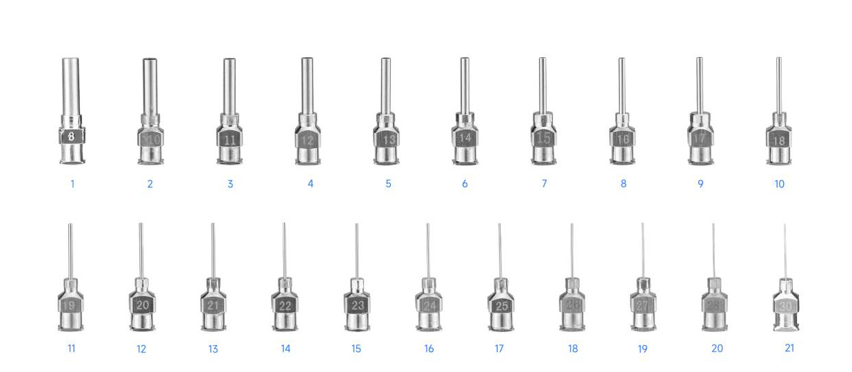
Selecting the optimal dispensing needle directly governs flow rate, shot repeatability, and process stability in automated and manual fluid dispensing systems. Choosing the correct tip sizing involves balancing fluid viscosity, required deposit size, operating pressure, and chemical compatibility.
Selecting an incorrect tip size or material style leads to excessive backpressure, fluid shearing, tip clogging, or irregular bead geometry. This technical guide provides a standardized dispensing needle gauge chart, breaks down the relationship between gauge numbers and physical dimensions, and outlines a structured selection framework for industrial adhesives, sealants, and lubricants.
Understanding Dispensing Needle Gauges: How Sizing Works
Industrial dispensing tips follow the Birmingham Gauge system (often abbreviated as Gauge or G). In this inverted scale, a higher gauge number corresponds to a smaller internal diameter (ID) and outer diameter (OD). For example, a 14G tip features a large internal bore for high-viscosity pastes, whereas a 34G tip delivers micro-deposits of low-viscosity fluids.
Gauge Sizing Logic:
Higher Gauge Number (e.g., 34G) ──> Smaller ID / OD ──> Micro-deposits / Low Viscosity
Lower Gauge Number (e.g., 14G) ──> Larger ID / OD ──> High Flow / High Viscosity
Key Dimensional Factors in Tip Selection
-
Internal Diameter (ID): The primary dimension governing fluid flow restriction. Flow resistance increases exponentially as the internal diameter decreases.
-
Outer Diameter (OD): Crucial when dispensing into narrow channels, tight component clearances, or deep cavities.
-
Tip Length: Standard length is typically 0.5 inches (12.7 mm), though shorter (0.25 in) or longer (1.0–1.5 in) options exist. Longer cannulas increase backpressure, requiring higher pressure settings.
-
Hub Design: Most precision systems use double-helix Luer Lock hubs to prevent needle blow-off under pressure.
To maintain precise fluid control across different automated lines, engineering teams select specialized adhesive dispense tips matching both fluid rheology and robot speed parameters.
Dispensing Needle Gauge Size Chart
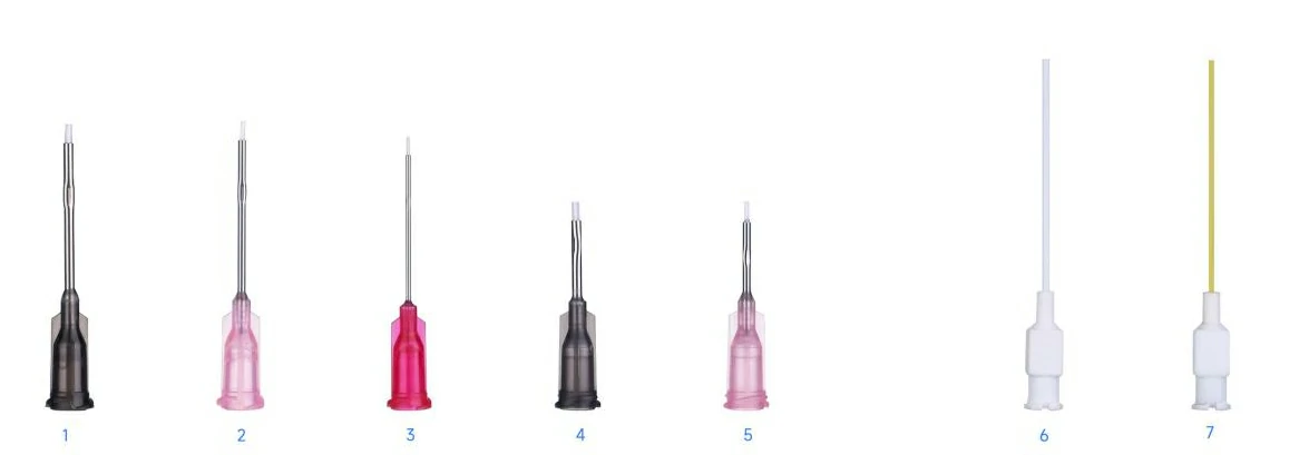
The following standard dispensing needle gauge chart outlines internal diameters, outer diameters, and color-coded hub conventions widely used in B2B manufacturing.
Note: Color-coding standardizations vary slightly by manufacturer. Dimensions should be verified against supplier technical datasheets prior to high-volume production.
| Gauge (G) | Color Code (Standard Hub) | Internal Diameter (in) | Internal Diameter (mm) | Outer Diameter (in) | Outer Diameter (mm) | Recommended Fluid Viscosity Range |
|---|---|---|---|---|---|---|
| 14G | Olive / Clear | 0.063 | 1.60 | 0.072 | 1.83 | Very High (> 50,000 cPs) |
| 15G | Amber / Gray | 0.054 | 1.37 | 0.072 | 1.83 | High (20,000 – 50,000 cPs) |
| 16G | Purple | 0.047 | 1.19 | 0.065 | 1.65 | High (10,000 – 30,000 cPs) |
| 18G | Green | 0.033 | 0.84 | 0.050 | 1.27 | Medium-High (5,000 – 20,000 cPs) |
| 20G | Pink | 0.023 | 0.60 | 0.036 | 0.91 | Medium (1,000 – 5,000 cPs) |
| 21G | Purple / Blue | 0.020 | 0.51 | 0.032 | 0.82 | Medium (1,000 – 3,000 cPs) |
| 22G | Blue | 0.016 | 0.41 | 0.028 | 0.72 | Medium-Low (500 – 1,500 cPs) |
| 23G | Orange | 0.013 | 0.33 | 0.025 | 0.64 | Low (100 – 1,000 cPs) |
| 25G | Red | 0.010 | 0.25 | 0.020 | 0.51 | Low (1 – 500 cPs) |
| 27G | Clear / Yellow | 0.008 | 0.20 | 0.016 | 0.41 | Very Low Water-like (< 100 cPs) |
| 30G | Lavender | 0.006 | 0.15 | 0.012 | 0.31 | Micro-dispensing (< 50 cPs) |
| 32G | Yellow / Opal | 0.004 | 0.10 | 0.009 | 0.23 | Ultra-micro dispensing |
| 34G | Snow / Teal | 0.002 | 0.06 | 0.007 | 0.18 | Precision micro-dots |
For production applications requiring specialized tip geometries, non-standard lengths, or unique hub threads, manufacturers often utilize custom dispensing tip solutions tailored to specific automated equipment.
How to Select the Right Gauge Based on Fluid Viscosity & Application
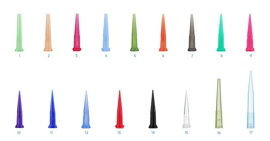
Fluid viscosity measures a material’s resistance to flow, expressed in centipoise (cPs). Selecting the wrong tip gauge relative to viscosity creates severe process instability:
-
Gauge too small: Causes high backpressure, fluid shearing, slow cycle times, or system failure.
-
Gauge too large: Leads to poor bead control, drooling, excessive shot sizes, and material waste.
Selection Flow:
1. Identify Material Viscosity (cPs)
2. Determine Required Dot/Bead Diameter (mm)
3. Match to Needle Gauge Sizing
4. Select Tip Material (Stainless Steel, Tapered, or Polypropylene)
Viscosity-to-Gauge Selection Matrix
| Fluid Category | Typical Viscosity (cPs) | Common Material Examples | Recommended Gauge Range |
| Water-Thin | 1 – 100 | Cyanoacrylates (Instant Glues), Solvents, Primers | 25G – 34G |
| Low Viscosity | 100 – 1,000 | Conformal Coatings, Light Oils, UV-Curable Resins | 21G – 25G |
| Medium Viscosity | 1,000 – 10,000 | Anaerobics, RTV Silicones, Solder Masks, Epoxies | 18G – 22G |
| High Viscosity | 10,000 – 50,000 | Heavy Greases, Structural Epoxies, Polyurethanes | 15G – 18G |
| Paste / Gel | > 50,000 | Thermal Pastes, Filled Solders, Thick Sealants | 14G – 16G (Tapered) |
Choosing the Right Tip Material & Style: Stainless Steel vs. Tapered vs. Flexible
Beyond gauge size, the material construction and physical profile of the tip dictate fluid behavior, surface safety, and clogging resistance.
1. Stainless Steel Straight Needles
-
Construction: Rigid 304 or 316 stainless steel cannula inserted into a polypropylene Luer Lock hub.
-
Best For: General-purpose dispensing of solvents, oils, epoxies, and cyanoacrylates.
-
Advantages: High dimensional accuracy, solvent resistance, and mechanical rigidity for precise vertical placement.
2. Tapered Smooth Flow Tips (Polyethylene / Polypropylene)
-
Construction: Molded conical shape that tapers from a wide hub down to the final orifice.
-
Best For: Thick gels, silicones, thermal compounds, and particle-filled pastes.
-
Advantages: Significantly lowers backpressure compared to straight tubing, allowing lower pneumatic pressure, faster line speeds, and reduced air entrapment.
3. Flexible Polypropylene Tips
-
Construction: Soft plastic cannula that flexes upon contact.
-
Best For: Dispensing into scratch-sensitive electronics, blind holes, or uneven surfaces.
-
Advantages: Prevents scratching on delicate substrates; easily cut to custom lengths if needed.
4. PTFE-Lined / Shielded Tips
-
Construction: Stainless steel needle with an internal PTFE lining or opaque UV-blocking shell.
-
Best For: Fast-curing cyanoacrylates and light-sensitive (UV) adhesives.
-
Advantages: Prevents premature fluid curing or clogging inside the cannula during line pauses.
Tip Material & Style Comparison
| Tip Style | Material | Flow Efficiency | Resistance to Clogging | Scratch Safety | Ideal Adhesives/Fluids |
| Straight Needle | Stainless Steel | Standard | Moderate | Low | Epoxies, Solvents, Oils |
| Tapered Tip | Polyethylene | High | High | High | Gels, Silicones, Pastes |
| Flexible Tip | Polypropylene | Standard | Moderate | Very High | Delicate Substrates, Cyanoacrylates |
| PTFE-Lined | PTFE / Metal | High | High (Anti-Clog) | Moderate | Light-Curing & Fast-Setting Glues |
Common Dispensing Errors and Troubleshooting
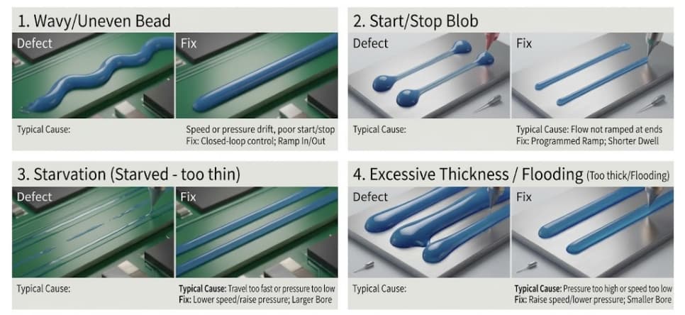
When dispensing performance degrades, incorrect tip selection is often the root cause. Use this troubleshooting guide to identify and correct process defects.
1. Excessive Backpressure or Slow Flow
-
Symptoms: Fluid dispenses too slowly; valve response lags; pressure regulators must be set dangerously high.
-
Causes: Gauge size is too small for the fluid’s viscosity, or cannula length is unnecessarily long.
-
Solution: Increase needle size by 1–2 gauge steps, or switch from a straight stainless steel tip to a smooth-flow tapered tip.
2. Tailed or Stringing Deposits
-
Symptoms: Fluid forms a long string or tail when the dispensing head retracts.
-
Causes: Fluid surface tension and viscosity resist clean breaking; nozzle orifice diameter mismatch.
-
Solution: Decrease gauge size (smaller orifice creates higher shear to break the tail), adjust valve pullback/vacuum retractions, or switch to a tapered tip.
3. Frequent Needle Clogging
-
Symptoms: Deposit volume decreases over time until fluid stops entirely.
-
Causes: Moisture-sensitive or light-curable fluid reacting inside the steel cannula; particle-filled pastes bridging across a small orifice.
-
Solution: Use opaque/UV-blocking tips for light-sensitive materials, PTFE-lined tips for cyanoacrylates, or select an orifice size at least 3–5 times larger than the largest particle in filled pastes.
4. Substrate Scratching or Tip Bending
-
Symptoms: Automated z-axis height variation causes rigid needles to mar parts or bend out of alignment.
-
Solution: Transition to flexible polypropylene dispensing tips or integrate height-sensing surface detection.
Custom Needles and OEM/ODM Manufacturing Considerations
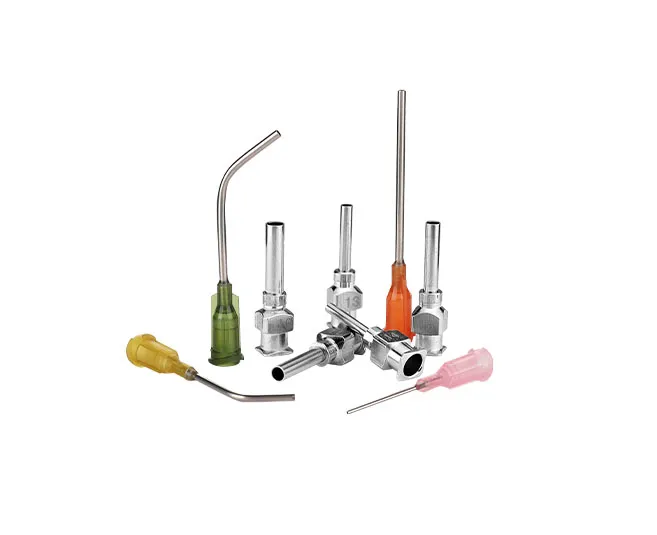
Standard off-the-shelf dispensing tips meet most general industrial needs. However, specialized medical devices, automotive electronics, and automated micro-dispensing cells frequently require custom configurations.
When evaluating custom production, manufacturing engineers should confirm:
-
Custom Gauge & ID Tolerances: Specialized inner diameter tolerances to ensure ultra-precise volumetric repeatability across high-speed automated lines.
-
Custom Cannula Lengths & Angles: Bent needles (e.g., 45° or 90° bends) designed for reaching internal wall cavities or side channels.
-
Hub Threading & Color Matching: Custom Luer Lock geometries, specialized hub materials for aggressive chemicals, or proprietary color-coding systems
To evaluate custom tip configurations or request engineering samples, contact the Haijing engineering support team.
Key Takeaways
-
Gauge Size Relation: Dispensing needle gauges use an inverted scale; higher gauge numbers represent smaller internal diameters (e.g., 34G is micro-dispensing, 14G is high-flow paste dispensing).
-
Viscosity Matching: Low-viscosity fluids (< 1,000 cPs) require small gauges (23G–34G) to prevent drooling. High-viscosity gels and pastes (> 10,000 cPs) require larger gauges (14G–18G) or tapered profiles to minimize pressure.
-
Tip Geometry Matters: Tapered plastic tips reduce backpressure and speed up cycle times for thick fluids. Stainless steel needles offer high rigidity and precision for straight-line micro-deposits.
-
Avoid Clogging in Filled Fluids: Ensure the needle internal diameter is at least 3 to 5 times larger than the particle size of filled epoxies or pastes to prevent mechanical bridging and tip blockage.
Frequently Asked Questions (FAQ)
How do I accurately measure a dispensing needle’s inner diameter?
Inner diameter is measured using pin gauges, optical comparators, or digital micro-calipers. Because wall thickness varies between standard and thin-wall cannula designs, outer diameter measurements cannot reliably determine the inner diameter.
What is the difference between Luer Lock and Luer Slip tip hubs?
A Luer Lock hub features a threaded double-helix outer collar that twists and locks securely onto the dispensing syringe or valve, preventing blow-off under pressure. A Luer Slip hub relies solely on friction fit and is intended only for non-pressurized or manual application.
Can stainless steel dispensing needles be cleaned and reused?
While all-metal needles can be cleaned using compatible solvents or ultrasonic baths, standard plastic-hub dispensing needles are designed as disposable single-use items. Cleaning reusable needles often leaves residual cured material or damages internal surface smoothness, compromising deposit repeatability.
Contact Haijing for comprehensive technical support
Need assistance selecting the right dispensing needle gauge for your automated line or specialized adhesive? Contact our technical engineering team at Haijing to share your fluid viscosity, required deposit geometry, and operating pressure parameters. We provide technical consultations, custom OEM/ODM tip prototyping, and high-volume production samples.
Gauge is only one part of outlet selection. Use the dispensing nozzle versus mixing nozzle guide to decide whether the process needs deposit control, in-line mixing, or both.