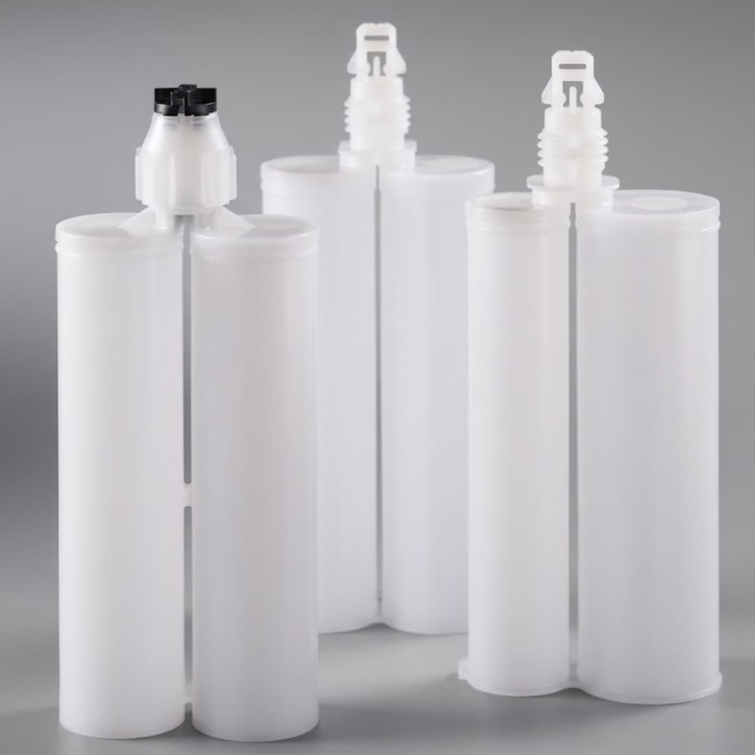
Bond line thickness—the cured gap between two adhered surfaces—is one of the few process variables that quietly controls whether a joint meets spec or fails in the field. Too thick and the adhesive wastes material, slows cure, and can trap stress; too thin and you lose strength, starve the bond, or bridge contaminants. This guide covers what actually drives bead geometry, how to match nozzle and process to a target bond line, and how to verify and hold that thickness across a production run.
Why Bond Line Thickness Controls Joint Performance
Bond line thickness sits at the intersection of strength, cure, and stress:
- Strength: many structural adhesives reach peak lap-shear at a defined bond line; far above or below it, properties fall.
- Cure behavior: thicker lines hold more mixed material, so exotherm and through-cure time change with thickness—relevant for two-part systems.
- Stress and fatigue: a controlled, uniform line spreads load; an uneven line concentrates it at edges and ends.
- Sealing and thermal paths: in electronics and thermal interfaces, the line sets the dielectric gap or the thermal resistance.
For electronics and thermal interfaces, the same line that bonds also sets electrical clearance or heat flow, so consistency matters as much as the average value. The electronics dispensing context shows where line control is tightest.
What Drives Bead Geometry (the Variables)
Bead width, height, and therefore bond line are set by a short list of interacting variables:
| Variable | How it shifts the deposit |
|---|---|
| Nozzle bore / tip ID | Larger bore → wider, higher deposit at fixed pressure |
| Dispense pressure | Higher pressure → faster fill, wider/heavier bead |
| Travel speed | Faster travel → thinner, narrower bead for the same output |
| Material viscosity | Higher viscosity → needs more pressure or slower travel |
| Surface energy / wet-out | Poor wet-out leaves a narrower effective bond than the deposit |
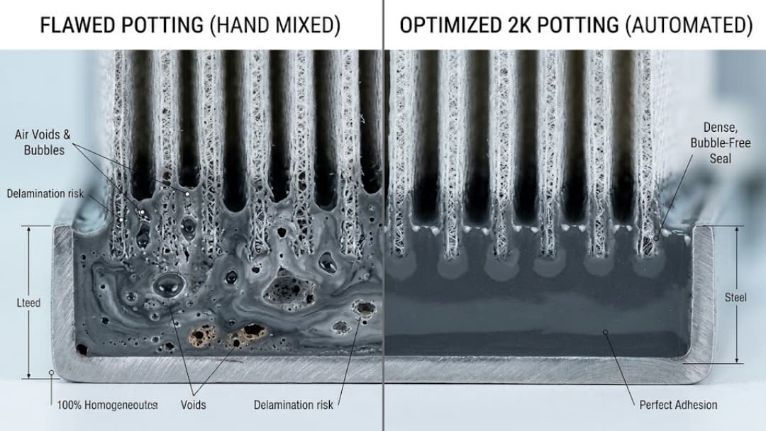
| Mix uniformity (2K) | Inconsistent mix changes flow and cure, so the line varies |
| Temperature | Warmer material flows easier, widening the deposit |
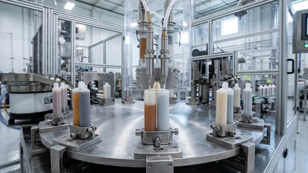
Because they interact, the line is really an output of pressure × speed × bore × material, not any single knob. A static or dynamic mixer that delivers uniform mix keeps the flow term steady so the other variables can be tuned predictably.
Matching Nozzle and Deposit to the Target BLT
The nozzle is the cheapest and fastest lever on bead geometry, but only if matched to the target:
- Target a line, not a dot: a round-hole tip lays a rounded bead whose width and height scale with bore; pick the bore that hits the target width at your pressure and speed.
- Fan or slot tips spread material into a flat ribbon for gasketing or wide bonds where a round bead would starve the edges.
- Needle tips give fine, low-volume deposits for small parts and tight BLT windows.
- Tapered vs straight bore changes pressure drop and thus deposit consistency at the start/stop of a bead.
Select the tip so the target bond line falls in the middle of its comfortable range, not at the limit—running a tip at its edge makes the line sensitive to any pressure or speed drift. The dispensing tip selection guide maps tip geometry to deposit profiles.
Robotic Path and Process Control for Repeatability
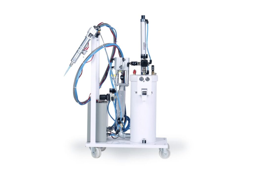
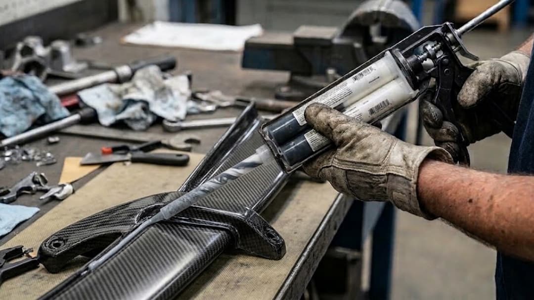
Hand dispensing cannot hold a bond line across thousands of parts. A dispensing robot holds it by controlling the variables that hand work lets drift:
- Constant travel speed through corners and straight runs, so the bead does not balloon at stops or thin on acceleration.
- Pressure or flow closed-loop that compensates for viscosity shift as the material warms or the cartridge empties.
- Start/stop control—ramping flow in and out to avoid the classic stop blob and start starved bead.
- Multi-axis synchronization for 3D paths so bead width stays uniform on changing geometry.
The point is repeatability: the same program, the same line, part after part. Where mixed material is involved, pairing the robot with a consistent mixer removes mix-driven flow variation from the equation.
Measuring and Verifying Bond Line Thickness
You cannot hold what you do not measure. Common methods, roughly from fastest to most definitive:
| Method | What it gives | Best use |
|---|---|---|
| Weigh-out / shot mass | Average deposit volume per part | High-speed in-line check |
| Caliper / thickness gauge | Direct line thickness on simple joints | Setup and spot checks |
| Cured cross-section + microscopy | True line profile and uniformity | Qualification, failure analysis |
| Laser / optical profiling | Non-contact line height/width map | In-line or batch mapping |
Define the acceptable range and how often to check it in the process plan; for critical joints, qualify the line on a cured cross-section before volume runs. If you need help setting the acceptance window for your joint, the customization team can qualify it against your parts and adhesive.
Common Bead Defects and Their Fixes
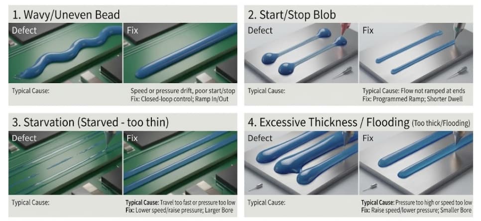
Most rejects trace to a handful of recognizable patterns:
| Defect | Typical cause | Fix |
|---|---|---|
| Wavy / uneven bead | Speed or pressure drift, poor start/stop | Closed-loop speed/pressure; ramp in/out |
| Start/stop blob | Flow not ramped at ends | Programmed ramp; shorter dwell |
| Starved (too thin) | Travel too fast or pressure too low | Lower speed or raise pressure; larger bore |
| Too thick / flooding | Pressure too high or speed too low | Raise speed or lower pressure; smaller bore |
| Stringing / tails | High viscosity, fast retract, no cutoff | Snuff-back or cutoff; slower retract |
| Inconsistent mix streaks | Weak mixer or ratio drift (2K) | Verify ratio; adequate mixer elements |
Each fix points back to one of the driving variables, which is why controlling them at the source beats chasing defects after the fact. Several of these—starving, flooding, and stringing—are directly tied to tip selection.
A BLT Control Checklist
Before a run, lock the line down:
Target
- Bond line target and acceptable range defined from the joint spec
- Acceptance method chosen (cross-section / gauge / weigh-out)
Hardware
- Nozzle bore/type matched to target BLT and deposit shape
- Dispensing robot program with constant speed and ramp control
- Mixer verified for uniform output (2K)
Process
- Pressure/speed set and closed-loop where needed
- Temperature within material’s working window
- First-article line measured before volume
Haijing’s customization engineers tune nozzle, robot, and mixer together against your adhesive and part so the bond line holds across the run.
Frequently Asked Questions
What is bond line thickness in adhesive joints?
It is the thickness of the cured adhesive layer between the two surfaces being joined. It is a controlled process variable because it affects joint strength, cure behavior, stress distribution, and—in electronics or thermal joints—electrical clearance or thermal resistance.
How do I control adhesive bead width and thickness?
Control the interacting variables: nozzle bore, dispense pressure, travel speed, and material viscosity. Pick a nozzle whose comfortable range covers your target line, hold travel speed constant (typically with a robot), and use closed-loop pressure to absorb viscosity drift. Measure the line and tune until it sits in the middle of the acceptable range.
Does nozzle size determine bond line thickness?
Largely, but not alone. Nozzle bore sets the deposit volume at a given pressure and speed, so it is the fastest lever—but pressure, travel speed, viscosity, and surface wet-out all shift the final line. Match the nozzle to the target and then control the other variables to hold it.
Why is my adhesive bead uneven or wavy?
Usually speed or pressure drift, or poor start/stop handling. Hand dispensing and uncompensated machines let travel speed or pressure wander, ballooning the bead at stops and thinning it on acceleration. A robot with constant-speed path control and ramped start/stop, plus closed-loop pressure, removes most of it.
How do I measure bond line thickness?
Weigh-out gives average deposit volume fast; a caliper or thickness gauge reads simple joints directly; a cured cross-section under a microscope shows the true profile and uniformity; laser or optical profiling maps the line non-contact. Choose by how definitive the check needs to be—qualify on a cross-section, then spot-check in production.
Conclusion
Bond line thickness is an output of nozzle, pressure, speed, viscosity, and mix uniformity acting together—not a single setting. Hold it by matching the nozzle to the target range, controlling travel speed and pressure (usually with a dispensing robot), keeping the mixer consistent for two-part materials, and verifying the line with the right measurement. Define the acceptable range up front, qualify on a cross-section, and the same bond line repeats part after part.
If you need to dial in a bond line on a new adhesive or part, send the joint drawing and material data to an applications engineer.
Contact Us: Send us your part drawing and adhesive data—our engineers will match the nozzle, robot program, and mixer to hold your target bond line. → customization