Why Your Dispensing Needle Keeps Clogging: Gauge Selection Mistakes to Avoid
A clogged dispensing needle directly halts automated production lines, alters cycle times, and causes inconsistent bead profiles. In most manufacturing operations, chronic clogging is not caused by defective adhesives, but by gauge selection errors, geometry mismatches, and particle bridge formations. Selecting the right needle requires balancing internal diameter (ID), fluid viscosity, particulate sizes, and flow dynamics.
This guide breaks down the engineering causes of needle blockage, analyzes common gauge sizing errors, compares straight versus tapered geometries, and provides an actionable framework to keep your dispensing line operating smoothly.
The Real Cost of Dispensing Needle Clogging on Industrial Lines
When an adhesive dispensing needle clogs, the impact extends beyond replacing a single consumable tip:
-
Production Line Downtime: Operators must stop cycles to purge, clean, or swap tips, resulting in immediate output loss.
-
Unstable Fluid Pressure: Clogs cause backpressure spikes in pneumatic dispensing guns and automated valves, leading to stringing, drooling, or sudden volume bursts once cleared.
-
Part Rejection and Rework: Incomplete fluid deposits compromise structural bonding, encapsulation, or sealing in sensitive electronics and semiconductor assembly.
-
Accelerated Wear on Dispensing Systems: Forcing high-viscosity materials through restricted orifices strains seals, pistons, and fluid delivery lines.
Identifying the root mechanical or fluid cause of the blockage prevents costly trial-and-error adjustments on the factory floor.
4 Critical Gauge & Tip Selection Mistakes That Trigger Needle Clogs
Fluid blockages typically occur when the physical constraints of the needle run counter to the rheological behavior of the adhesive.
1. Misunderstanding the Gauge System (Higher Gauge = Smaller Orifice)

Industrial needles follow the Stubs Iron Wire Gauge system, where a higher gauge number indicates a smaller inner diameter (ID). For example:
-
A 14-gauge needle provides a large inner opening (~1.60 mm ID).
-
A 30-gauge needle provides a micro-dispense opening (~0.15 mm ID).
Engineers or technicians seeking higher dispensing precision often jump to 27G–32G tips without evaluating fluid viscosity. Forcing thick fluids through an undersized cannula drastically increases fluid friction, causing local stagnation and premature drying inside the shaft.
2. Violating the “3x Rule” for Particle-Filled Adhesives
Filled adhesives—such as silver sintering pastes, thermally conductive greases, and ceramic-loaded epoxies—contain solid suspension particles.
The 3x Engineering Rule:
The inner diameter (ID) of the dispensing tip must be at least 3 to 5 times larger than the largest particle size (99th percentile of the particle size distribution) in the fluid formulation.
If a thermal paste contains 30-micron particles, an inner diameter under 90–150 microns causes particles to cluster at the needle entrance. This “bridging effect” stops fluid flow entirely, regardless of how much pneumatic pressure is applied.
3. Using Long, Straight Metal Needles for High-Viscosity Fluids
Standard stainless steel straight needles create substantial fluid drag along their internal length (often 0.5 to 1.5 inches). When handling medium-to-high-viscosity materials (such as RTV silicones, polyurethanes, or thick pastes), high wall friction causes:
-
Significant pressure drop across the needle length.
-
Fluid shear-thinning or shear-thickening anomalies.
-
Material stagnation along the inner walls, triggering early cure cycles.
4. Overlooking Fluid Chemistry and Ambient Reactivity
Certain chemistries react poorly with specific needle configurations:
-
Cyanoacrylates (Instant Adhesives): Cure rapidly when exposed to trace moisture. Steel cannulas can retain residual moisture or conduct ambient heat, polymerizing the glue directly inside the metal tube.
-
Two-Component Epoxies & Acrylics: If the mixed material sits inside the needle during intermittent pauses, cross-linking begins immediately. Using the proper static and dynamic mixers matched with low-retention tips is necessary to prevent cured plugs from migrating into the dispense tip.
The Solution: When to Switch to Tapered Dispensing Tips
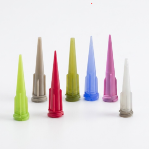
For medium-to-high-viscosity materials, standard straight metal cannulas can be replaced with tapered dispensing tips.
Tapered tips feature a conical fluid path molded from polyethylene (often with UV-blocking additives). The wide-entry back transition minimizes backpressure and delivers an unrestricted, smooth fluid flow.
| Evaluation Metric | Straight Stainless Steel Cannula | Smooth-Flow Tapered Dispense Tip |
| Internal Fluid Path | Constant narrow cylindrical bore | Conical transition from luer inlet to tip |
| Fluid Flow Resistance | High (friction along entire length) | Low (resistance limited to the exit orifice) |
| Clog Risk (Thick Pastes) | High | Minimal |
| Clog Risk (Filled Fluids) | High (prone to particle bridging) | Low (funnel shape prevents cluster jams) |
| Best-Fit Fluid Types | Solvents, low-viscosity UVs, micro-dots | Silicones, RTVs, sealants, solder pastes, greases |
| Recommended Products | Standard metal/plastic hubs | Precision tapered dispensing tips |
Engineering Selection Framework: Matching Fluid Viscosity to Gauge Size
Selecting the proper needle gauge requires coordinating fluid viscosity (in centipoise, cPs) with the appropriate tip structure and inner diameter.
Note: The parameters below serve as an engineering baseline. Exact flow rates depend on pressure settings, fluid rheology, and dispensing cycle speeds.
| Fluid Viscosity (cPs) | Example Fluid / Adhesive | Recommended Gauge Range | Recommended Tip Construction |
| 1 – 100 | Solvents, Cyanoacrylates, Primers | 25G – 32G | PTFE-lined or stainless steel straight cannula |
| 100 – 2,500 | Low-viscosity Epoxies, Light UV Inks | 21G – 25G | Stainless steel cannula or polypropylene tip |
| 2,500 – 20,000 | Standard Epoxies, Polyurethanes, Oils | 18G – 21G | Stainless steel straight or smooth-flow tapered tip |
| 20,000 – 100,000 | Silicones, RTVs, Solder Masks | 14G – 18G | Tapered dispensing tips (Polyethylene) |
| 100,000+ | Thermal Pastes, Structural Mastics | 14G – 16G | Tapered dispensing tips (High-flow orifice) |
Custom & OEM Dispensing Solutions for Complex Applications

Standard catalog tips cannot always resolve the tolerances required by high-precision, non-standard automated cells. Specialized fluid handling requires tailored components:
-
Custom Inner Diameters & Tight Tolerances: Critical for micro-dispensing applications in semiconductor wafer-level packaging.
-
Specialized Wetted Materials & Coatings: PTFE linings for moisture-sensitive cyanoacrylates, or anti-static (ESD-safe) compounds for electronics manufacturing.
-
Non-Standard Tip Lengths & Bends: 45-degree and 90-degree angled tips designed for robotic cells accessing recessed automotive housings.
Working with an experienced dispensing needle manufacturer allows industrial clients to develop custom configurations that match their equipment parameters. HaiJing provides precision-molded and machined solutions through its OEM and custom dispensing needle manufacturing services, ensuring reliable fluid control across global manufacturing operations.
Key Takeaways
-
Check the Gauge Logic: A higher gauge number means a smaller internal orifice. Always size by the actual inner diameter (mm/inch), not the gauge number alone.
-
Observe the Particle Clearance Rule: Ensure the needle ID is at least 3 to 5 times larger than the largest particle filler size in the compound.
-
Adopt Tapered Geometries for Thick Fluids: Replace long straight needles with conical tapered dispensing tips to lower backpressure and prevent fluid stagnation when handling pastes or silicones.
-
Match Material to Fluid Chemistry: Use PTFE-lined tips for cyanoacrylates and light-blocking opaque plastic tips for UV-cure adhesives.
Frequently Asked Questions (FAQ)
What is the primary difference between stainless steel and plastic tapered dispensing needles?
Stainless steel needles provide a rigid, uniform cylindrical bore suitable for low-viscosity fluids, micro-deposits, and solvent-based materials. Plastic tapered tips feature a conical fluid channel that reduces fluid resistance, making them more effective for dispensing high-viscosity pastes, silicones, and particle-filled materials without clogging.
How do I stop moisture-cure adhesives (like cyanoacrylates) from clogging the tip?
Moisture-cure adhesives react with ambient humidity and metal surfaces. Use specialized dispensing tips with moisture-resistant polyethylene or PTFE (Teflon) liners, and maintain a closed, dry-air nitrogen purge system on fluid reservoirs where necessary.
Can clogged industrial dispensing needles be cleaned and reused?
For precision industrial applications, cleaning disposable dispensing tips is not recommended. Residual cured adhesive, solvent degradation, or physical deformation of the orifice can alter flow rates and dispense volumes. Replacing low-cost consumables preserves line repeatability.
How does needle length affect dispensing pressure and clogging?
Flow resistance increases linearly with the length of the needle cannula. A longer needle requires higher dispensing pressure to achieve the same flow rate, which can lead to fluid separation, heat generation, or stagnation. Use the shortest practical needle length for high-viscosity fluids.
Contact Haijing for comprehensive technical support
Eliminating dispensing clogs requires aligning needle geometry with fluid rheology, filler particle sizes, and operating pressure. If your assembly line faces recurring tip blockage or erratic bead profiles, adjusting your needle gauge and tip design will stabilize your process.
Need assistance resolving needle clogging on your line?
Contact the fluid application team at HaiJing to evaluate your adhesive parameters, request complimentary sample test tips, or discuss custom OEM dispensing needles engineered for your production environment: Contact HaiJing Fluid Application Support.
A clog can originate in a final tip or in a mixed-material stack. The adhesive dispensing nozzle selection guide separates those functions and defines a pause-and-restart trial.