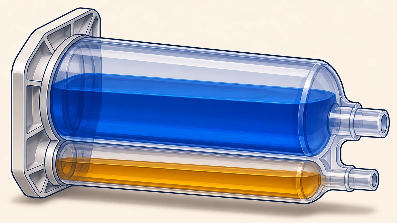
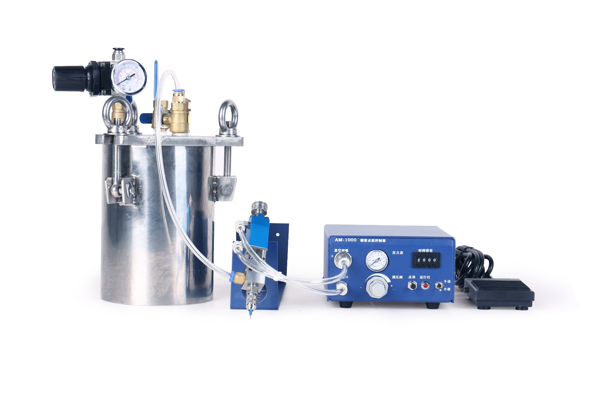
A dual adhesive cartridge can hold exactly 150 mL in total and still leave one component short. To verify fill capacity, specify the usable volume of chamber A and chamber B separately, mark where the fill ends, then measure each chamber on the same sample. A purchase order that says only “150 mL, 2:1” leaves the inspector without a limit for either side.
Consider an incoming inspection where the supplier reports 150 mL and the filling line cannot fit the required charge into the small barrel. Both observations can be true. Before changing the fill setting or rejecting the lot, ask for the two chamber readings and the drawing that shows how they were taken.
What capacity does the drawing actually promise?
A catalog size identifies a family. A volumetric ratio identifies the intended relationship between components. For example, Merlin’s ratio chart lists one 400 mL, 1:1 cartridge system as 200 mL on each side. That is enough information to shortlist the family. It still leaves open where to stop filling the physical sample and how much variation the buyer accepts. Merlin’s dual cartridge ratio charts.
For a specific part number, distinguish three quantities on the inspection sheet:
- Contained capacity at a reference position. The liquid volume enclosed by the specified chamber boundaries. The outlet recess, closure intrusion and product-facing contour of the piston can affect what is included.
- Usable fill capacity. The amount available for a charge after any specified air space or process allowance. If the fill plane already incorporates that allowance, deducting it again understates capacity.
- Actual production fill. The amount the filling process put into a particular package. An underfilled unit alone cannot tell you whether the chamber is too small.
Put the fill boundary and two limits on one drawing
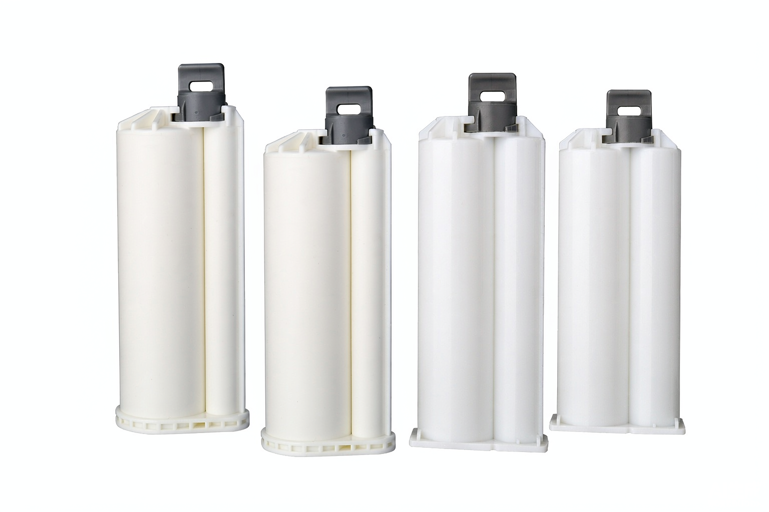
Mark A and B on an end view and state which end the reader is looking at. A photograph taken from the outlet end reverses left and right relative to a photograph taken from the filling end. Keep those A and B labels on the fixture, sample and inspection record. A tooling cavity number, if available, identifies a molding position and belongs in a separate field.
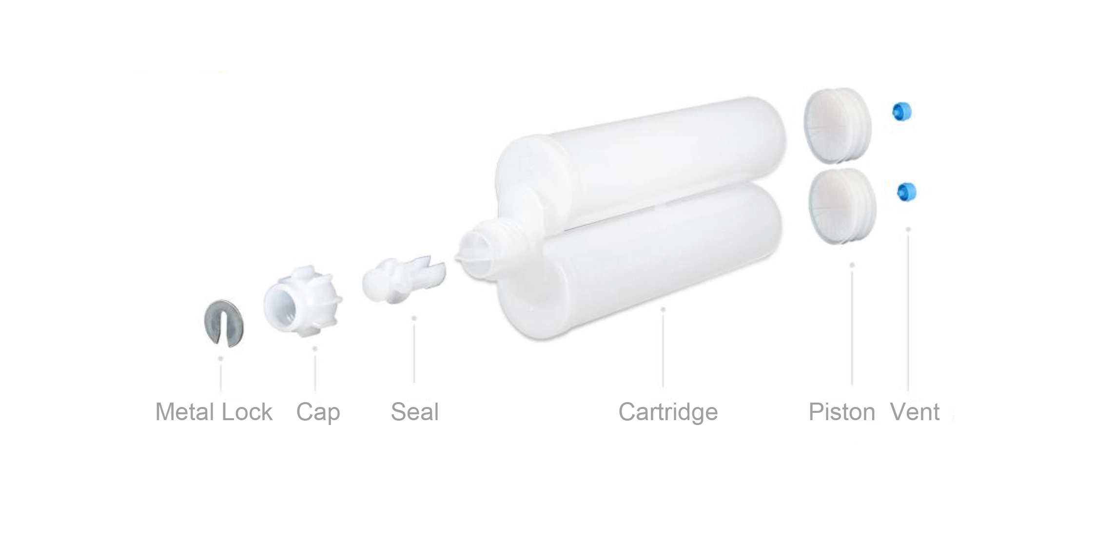
On a section view, dimension the endpoint from a reproducible housing surface. If the requirement is capacity under a seated piston, show which piston face defines the boundary, its installed depth and whether the outlet pocket counts. If inspection uses an open barrel filled to a line, define how to read the liquid surface. A line at the piston lip can give a different volume from the shaped face of an installed piston. An approved correlation or a fixture that reproduces that face is needed to use one measurement for the other.
Example purchase-order wording. “Measure chambers A and B per the fill plane and capped-outlet configuration on drawing [revision]. Record each usable volume in mL at [test temperature]. A must meet [lower and upper limits], B must meet [lower and upper limits]. Use method [revision], sample plan [reference] and decision rule [reference].” Where the buyer only needs a minimum charge, agree a lower limit and a separate closure-fit requirement if applicable. A two-sided tolerance needs a reason at both ends.
A drawing check helps isolate a misplaced reference plane or the wrong barrel revision. Our cartridge dimensional inspection guide covers the choice of datums. A matching outside diameter alone cannot establish the volume inside a molded part.
Measure both chambers on the same sample
A practical way to check a defined open fill plane is to weigh a compatible test liquid in each chamber. The principle is straightforward: contained volume (mL) = net liquid mass (g) ÷ liquid density at the test temperature (g/mL). NIST describes gravimetric volume measurement in its volumetric calibration procedures. A cartridge inspection still needs its own validated fixture, endpoint and uncertainty estimate.
- Prepare the tare. Record sample, lot, drawing revision, fixture and liquid IDs. Bring the sample and liquid to the agreed temperature. Seal the outlets as defined, dry the exterior and weigh the empty assembly with all hardware that will remain on the balance. Record this as m0.
- Fill A to its endpoint. Seat the assembly in the agreed orientation. Follow the same meniscus convention each time. Check for bubbles in the outlet pocket and droplets outside the barrel. Weigh the assembly as m1. The liquid mass in A is m1 − m0.
- Leave A in place and fill B. Use the same endpoint convention and record m2. B contains m2 − m1 of liquid by mass, provided A has neither leaked nor lost appreciable mass in the interval. If the setup requires changing caps, supports or pistons between weighings, use separately established tares for the changed configurations.
- Calculate and check each result. Use the documented density at the measured temperature. If working with production components, A and B may have different densities and need their own conversions. Keep the raw readings and compare the unrounded results with the agreed decision rule.
A thin test liquid that seeps past a temporary closure changes the result during weighing. A filled adhesive that traps air can reach the fill line with less liquid than expected. If the reference sample drifts or the endpoint cannot be read repeatedly, resolve the method before using the result to disposition the lot. For tight limits, have the measurement owner evaluate balance performance, density, temperature, endpoint repeatability and relevant corrections, including air buoyancy where material.
Worked example: the total passes and both chambers miss
This hypothetical inspection uses an open fill plane with the outlet capped and the same test liquid on both sides. Its density at the test temperature is 0.998 g/mL. The agreed example limits are 99.0–101.0 mL for A and 49.5–50.5 mL for B. For illustration, the parties compare the measured value directly to each limit. These are sample contract values, not published tolerances for a commercial cartridge.
The balance reads 34.000 g empty, 134.998 g after filling A, and 183.700 g after filling B. Subtract consecutive readings before converting to volume:
| Reading | Net liquid mass | Volume, rounded | Decision |
|---|---|---|---|
| Chamber A | 100.998 g | 101.2 mL | Above the 101.0 mL upper limit |
| Chamber B | 48.702 g | 48.8 mL | Below the 49.5 mL lower limit |
| Combined | 149.700 g | 150.0 mL | Matches nominal total; sample fails the two chamber limits |
The small barrel would be short by 1.2 mL against its 50 mL target. Extra room in A cannot hold the missing B component. If a real result falls close enough to a limit for measurement uncertainty to affect acceptance, apply the agreed uncertainty rule and retain the underlying readings. A single failed sample triggers the agreed sampling or containment action; its two readings are insufficient to estimate a lot defect rate.
When the supplier and receiving inspector get different answers
Both chambers read low. First compare endpoint depth, outlet inclusion, headspace treatment and liquid density. If the teams measured to different piston positions, repeat on a marked retained sample with the same fixture before asking for a tooling change.
Only one side reads low. Check side identity, bubbles and leakage, then repeat under the agreed method on another traceable sample. If the difference persists on one side across samples, retain the part and record its molding cavity mark where available. Ask the supplier to compare the internal profile and component revisions against an accepted sample.
The package passes but the delivered mix is off ratio. Contained volume answers how much liquid fits at rest. Delivered ratio depends on what actually exits each side during dispensing. Keep the capacity record and investigate output separately. Raising the fill limit to correct an output problem can obscure the cause.
Two questions before approving a replacement
Can we inspect an opaque cartridge without seeing the fill line?
Agree a physical endpoint that can be reproduced, such as a vented reference fixture set to a controlled depth. Validate that it represents the specified liquid boundary and does not trap a variable air pocket. Record which fixture was used so the supplier can reproduce the reading.
Can we use the same capacity report after a piston change?
Compare the product-facing contour and installed position of the two pistons first. An open-plane measurement on an unchanged barrel may still describe that barrel. If the accepted capacity is defined under the installed piston, establish whether the new assembly preserves that boundary before carrying the result over.